3 displaying port isolation configuration, 4 port isolation configuration example, I. network requirements – H3C Technologies H3C S3100 Series Switches User Manual
Page 152: Ii. network diagram
Operation Manual – Port Isolation
H3C S3100-52P Ethernet Switch
Chapter 1 Port Isolation Configuration
1-2
1.3 Displaying Port Isolation Configuration
After the above configuration, you can execute the display command in any view to
display the result of your port isolation configuration, thus verifying your configuration.
Table 1-2
Display port isolation configuration
Operation
Command
Description
Display information about
the Ethernet ports added to
the isolation group
display isolate port
You can execute the
display
command in any
view.
1.4 Port Isolation Configuration Example
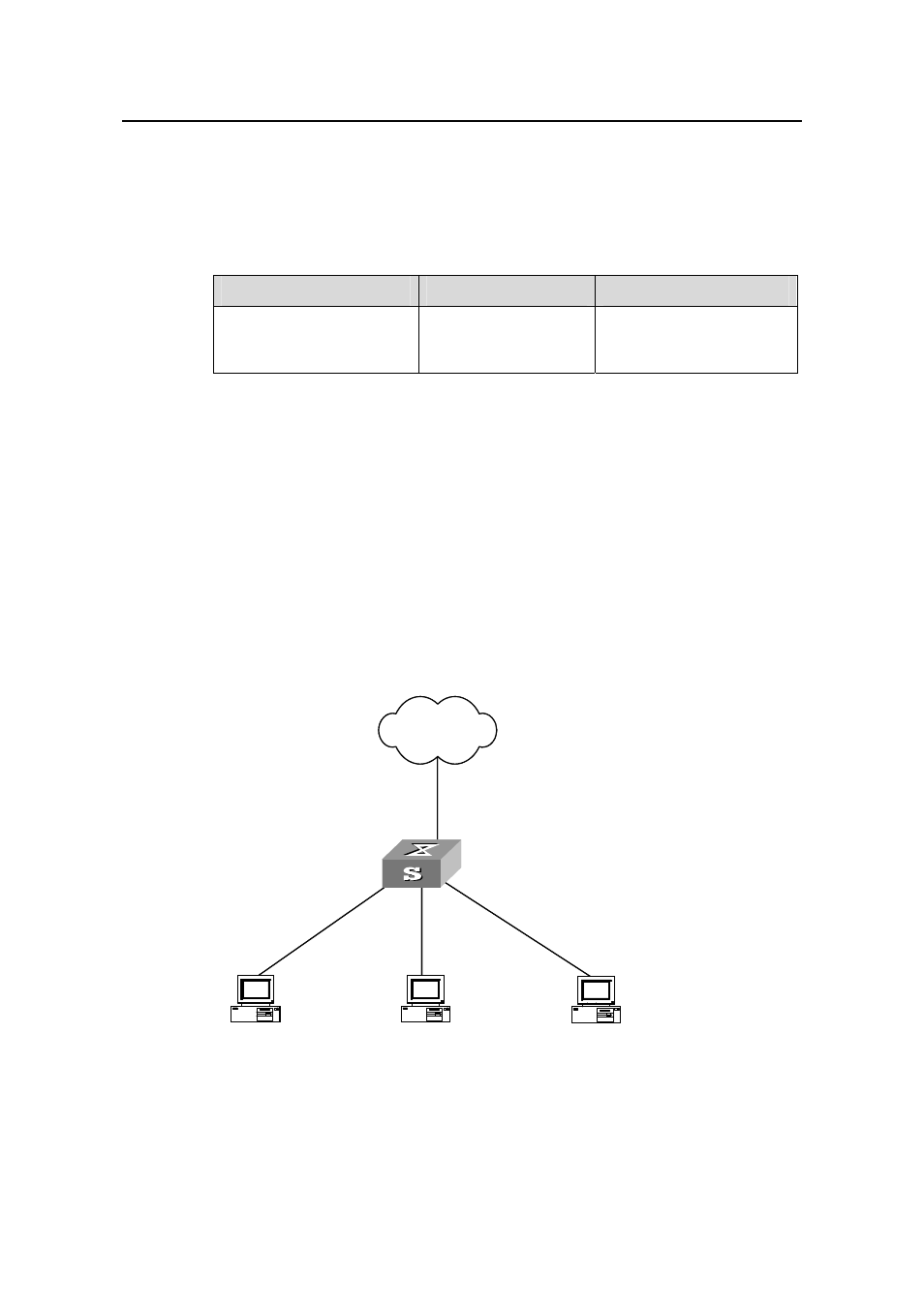
I. Network requirements
z
PC2, PC3 and PC4 connect to the switch ports Ethernet1/0/2, Ethernet1/0/3, and
Ethernet1/0/4 respectively.
z
The switch connects to the Internet through Ethernet1/0/1.
z
It is desired that PC2, PC3 and PC4 are isolated from each other so that they
cannot communicate with each other.
II. Network diagram
Internet
Ethernet1/0/2
Ethernet
Ethernet1/0/1
PC2 PC3
Switch
Ethernet1/0/3
1/0/4
PC4
Internet
Ethernet1/0/2
Ethernet
Ethernet1/0/1
PC2 PC3
Switch
Ethernet1/0/3
1/0/4
PC4
n
Figure 1-1
Network diagram for port isolation configuratio