X. port state – H3C Technologies H3C S3100 Series Switches User Manual
Page 179
Operation Manual – MSTP
H3C S3100-52P Ethernet Switch
Chapter 1 MSTP Configuration
1-4
z
A master port connects an MST region to the common root. The path from the
master port to the common root is the shortest path between the MST region and
the common root.
z
A region edge port is located on the edge of an MST region and is used to connect
one MST region to another MST region, an STP-enabled region or an
RSTP-enabled region
z
An alternate port is a backup port of a master port. It becomes the master port if
the existing master port is blocked.
z
A loop occurs when two ports of a switch are connected to each other. In this case,
the switch blocks one of the two ports. The blocked port is a backup port.
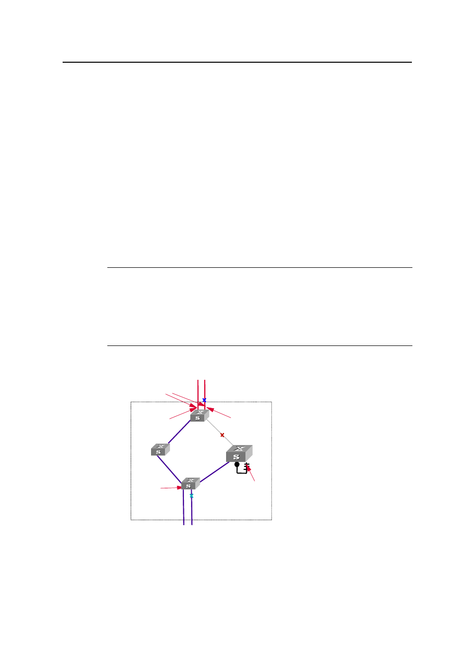
In Figure 1-2, switch A, switch B, switch C, and switch D form an MST region. Port 1
and port 2 on switch A connect upstream to the common root. Port 5 and port 6 on
switch C form a loop. Port 3 and port 4 on switch D connect downstream to other MST
regions. This figure shows the roles these ports play.
Note:
z
A port can play different roles in different MSTIs.
z
The role a region edge port plays is consistent with the role it plays in the CIST. For
example, port 1 on switch A in Figure 1-2 is a region edge port, and it is a master
port in the CIST. So it is a master port in all MSTIs in the region.
MST region
C
A
B
D
Port 4
Port 1
Port 2
Connected to the
common root
EdgePort
Master
port
Alternate port
Designated
port
Backup
port
Port 3
Port 5
Port 6
Figure 1-2
Port roles
X. Port state
Ports can be in one of the following three states: