3 principle of mstp, I. calculate the cist, Ii. calculate an msti – H3C Technologies H3C S3100 Series Switches User Manual
Page 180: Iii. implement stp algorithm, 3 principle of mstp -5
Operation Manual – MSTP
H3C S3100-52P Ethernet Switch
Chapter 1 MSTP Configuration
1-5
z
Forwarding state: Ports in this state can forward user packets and receive/send
BPDU packets.
z
Learning state: Ports in this state can receive/send BPDU packets.
z
Discarding state: Ports in this state can only receive BPDU packets.
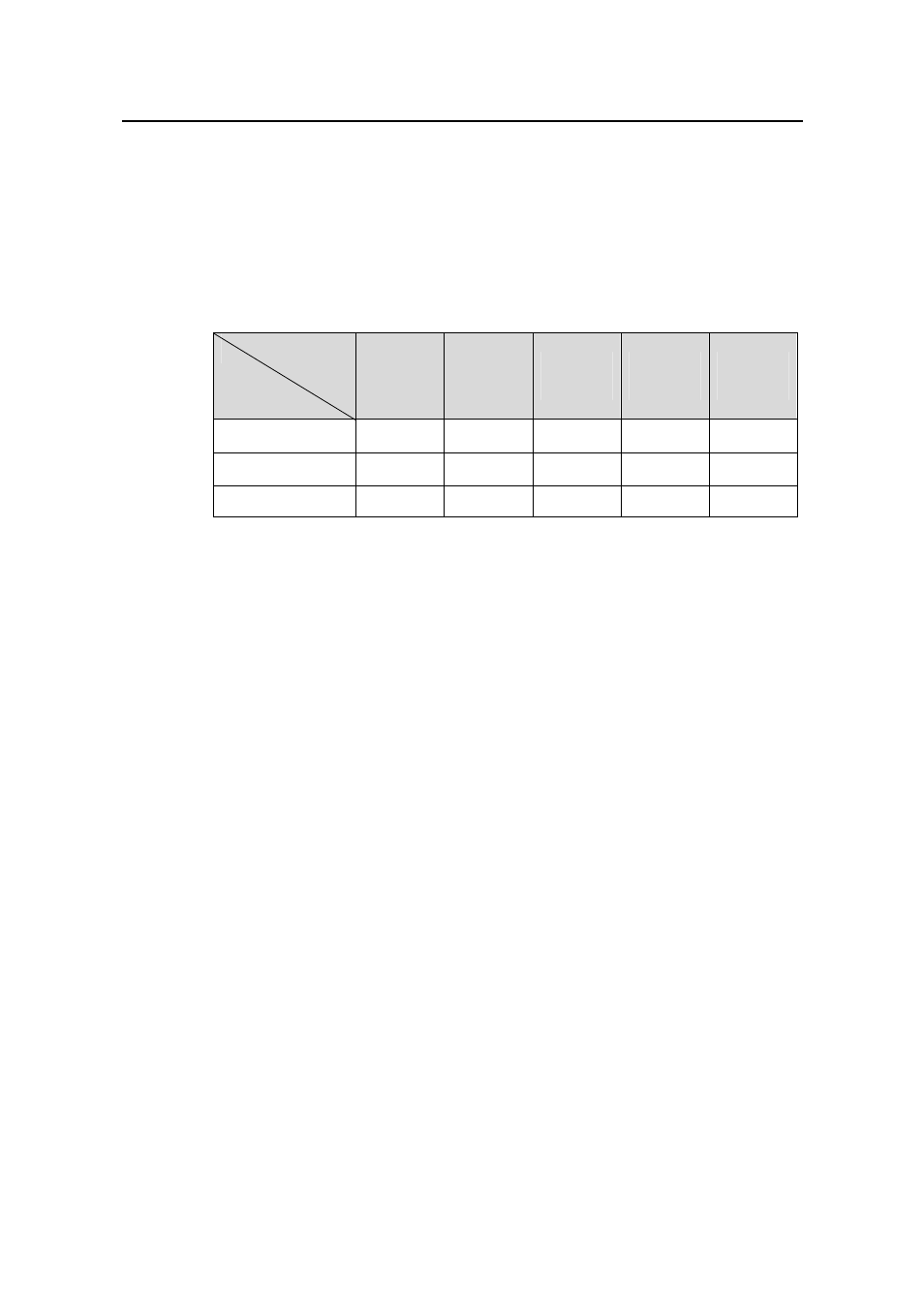
Port roles and port states are not mutually dependent. Table 1-1 lists possible
combinations of port states and port roles.
Table 1-1
Combinations of port states and port roles
Root/
port/Mast
er port
Designat
ed port
Region
edge port
Alternate
port
Backup
port
Forwarding
√
√
√
—
—
Learning
√
√
√
—
—
Discarding
√
√
√
√
√
Port
role
Port
state
1.1.3 Principle of MSTP
MSTP divides a Layer 2 network into multiple MST regions. The CSTs are generated
between these MST regions, and multiple spanning trees (also called MSTIs) can be
generated in each MST region. As well as RSTP, MSTP uses configuration BPDUs for
spanning tree calculation. The only difference is that the configuration BPDUs for
MSTP carry the MSTP configuration information on the switches.
I. Calculate the CIST
Through comparing configuration BPDUs, the switch of the highest priority in the
network is selected as the root of the CIST. In each MST region, an IST is calculated by
MSTP. At the same time, MSTP regards each MST region as a switch to calculate the
CSTs of the network. The CSTs, together with the ISTs, form the CIST of the network.
II. Calculate an MSTI
In an MST region, different MSTIs are generated for different VLANs based on the
VLAN-to-MSTI mappings. Each spanning tree is calculated independently, in the same
way as how STP/RSTP is calculated.
III. Implement STP algorithm
In the beginning, each switch regards itself as the root, and generates a configuration
BPDU for each port on it as a root, with the root path cost being 0, the ID of the
designated bridge being that of the switch, and the designated port being itself.
1) Each switch sends out its configuration BPDUs and operates in the following way
when receiving a configuration BPDU on one of its ports from another switch: