Ii. network diagram, Iii. configuration procedure – H3C Technologies H3C S3100 Series Switches User Manual
Page 615
Operation Manual – VLAN VPN
H3C S3100-52P Ethernet Switch
Chapter 1 VLAN-VPN Configuration
2-4
II. Network diagram
Ethernet1/0/1
Customer1
Custom
Provider1
Ethernet1/0/4
er2
Provider2
VLAN 2
VLAN 4
Ethernet1/0/3
Ethernet1/0/2
Trunk
Ethernet1/0/1
Customer1
Custom
Provider1
Ethernet1/0/4
er2
Provider2
VLAN 2
VLAN 4
Ethernet1/0/1
Customer1
Custom
Provider1
Ethernet1/0/4
er2
Provider2
VLAN 2
VLAN 4
Ethernet1/0/3
Ethernet1/0/2
Ethernet1/0/3
Ethernet1/0/2
Trunk
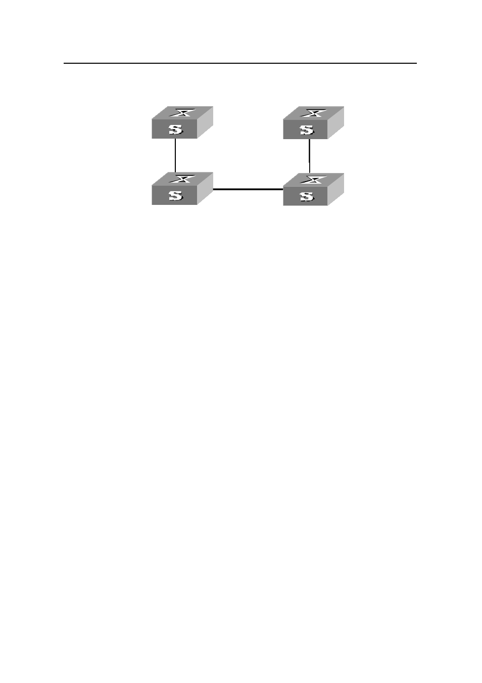
Figure 2-4
Network diagram for BPDU Tunnel configuration
III. Configuration procedure
1) Configure
Provide1.
# Enable the BPDU Tunnel fuction for NDP packets on port Ethernet1/0/1.
[H3C] interface Ethernet 1/0/1
[H3C-Ethernet1/0/1] undo ndp enable
[H3C-Ethernet1/0/1] bpdu-tunnel ndp
# Set the port Ethernet 1/0/2 to be a BPDU Tunnel uplink port.
[H3C-Ethernet1/0/1] quit
[H3C] interface Ethernet 1/0/2
[H3C-Ethernet1/0/2] bpdu-tunnel uplink
2) Configure
Provider2.
# Set the port Ethernet 1/0/3 to be a BPDU Tunnel uplink port.
[H3C] interface Ethernet 1/0/3
[H3C-Ethernet1/0/3] bpdu-tunnel uplink
# Enable the BPDU Tunnel function for NDP packets on port Ethernet1/0/4
[H3C-Ethernet1/0/3] quit
[H3C] interface Ethernet 1/0/4
[H3C-Ethernet1/0/4] undo ndp enable
[H3C-Ethernet1/0/4] bpdu-tunnel ndp