Ii. network diagram, Iii. configuration procedure – H3C Technologies H3C S3100 Series Switches User Manual
Page 271
Operation Manual – Routing Protocol
H3C S3100-52P Ethernet Switch
Chapter 2 Static Route Configuration
2-4
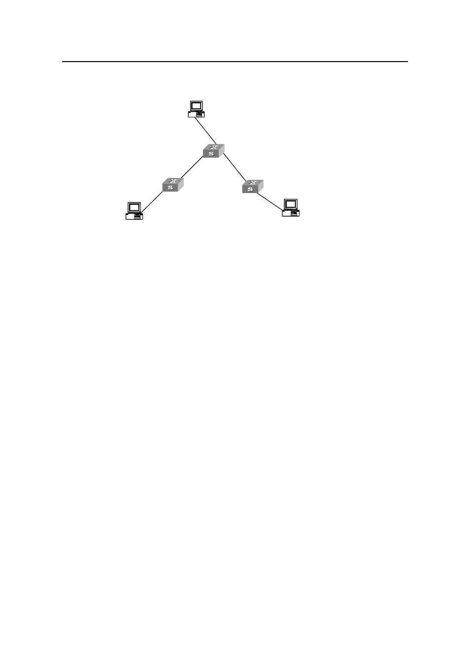
II. Network diagram
Host A
1.1.5.2/24
1.1.5.1/24
1.1.2.2/24
1.1.2.1/24
1.1.1.1/24
1.1.1.2/24
1.1.3.1/24
1.1.3.2
Sw itch A
Sw itch B
Sw itch C
1.1.4.2/24
/24
1.1.4.1/24
Host C
Host B
Host A
1.1.5.2/24
1.1.5.1/24
1.1.2.2/24
1.1.2.1/24
1.1.1.1/24
1.1.1.2/24
1.1.3.1/24
1.1.3.2
Sw itch A
Sw itch B
Sw itch C
1.1.4.2/24
/24
1.1.4.1/24
Host C
Host C
Host B
Host B
Figure 2-1
Static route configuration
III. Configuration procedure
# Configure static routes on Switch A.
[Switch A] ip route-static 1.1.3.0 255.255.255.0 1.1.2.2
[Switch A] ip route-static 1.1.4.0 255.255.255.0 1.1.2.2
[Switch A] ip route-static 1.1.5.0 255.255.255.0 1.1.2.2
# Configure static routes on Switch B.
[Switch B] ip route-static 1.1.2.0 255.255.255.0 1.1.3.1
[Switch B] ip route-static 1.1.5.0 255.255.255.0 1.1.3.1
[Switch B] ip route-static 1.1.1.0 255.255.255.0 1.1.3.1
# Configure static routes on Switch C.
[Switch C] ip route-static 1.1.1.0 255.255.255.0 1.1.2.1
[Switch C] ip route-static 1.1.4.0 255.255.255.0 1.1.3.2
# Configure the default gateway of Host A to 1.1.5.1.
[Switch A] ip route-static 0.0.0.0 0.0.0.0 1.1.5.1
# Configure the default gateway of Host B to 1.1.4.1.
[Switch B] ip route-static 0.0.0.0 0.0.0.0 1.1.4.1
# Configure the default gateway of Host C to 1.1.1.1.
[Switch C] ip route-static 1.1.1.0 255.255.255.0 1.1.1.1
Now, all the hosts/switches in the figure can interconnect with each other.