5 vlan-vpn configuration example, I. network requirements, Ii. network diagram – H3C Technologies H3C S3100 Series Switches User Manual
Page 610: Iii. configuration procedure, 5 vlan-vpn configuration example -6
Operation Manual – VLAN VPN
H3C S3100-52P Ethernet Switch
Chapter 1 VLAN-VPN Configuration
1-6
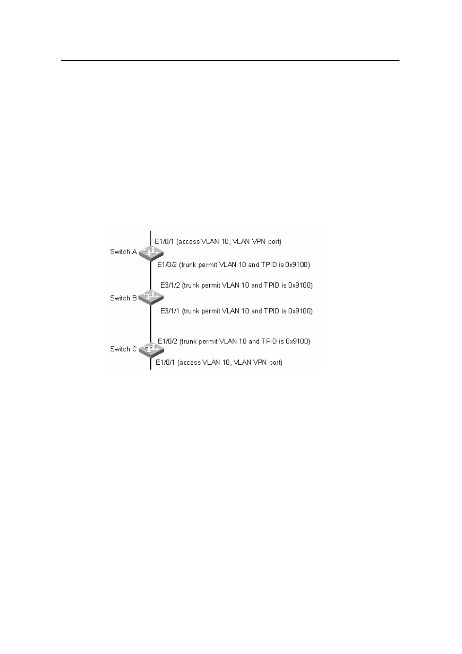
1.5 VLAN-VPN Configuration Example
I. Network requirements
z
Switch A and Switch C are S3100-52P switch. Switch B is a switch coming from
another manufacturer, which uses the TPID value of 0x9100.
z
Two user networks are connected to the Ethernet1/0/1 ports of Switch A and
Switch C respectively.
z
Switch B only permits packets of VLAN 10.
z
It is required that packets of the VLANs other than VLAN 10 can be exchanged
between the user networks connected to Switch A and Switch C.
II. Network diagram
Figure 1-4
Network diagram for VLAN-VPN configuration
III. Configuration Procedure
1) Configure Switch A and Switch C.
As the configuration performed on Switch A and Switch C is the same, configuration on
Switch C is omitted.
# Set the TPID value of Ethernet1/0/2 port of Switch A to 0x9100, and add the port to
VLAN 10.
[SwitchA] vlan 10
[SwitchA-vlan10] quit
[SwitchA] interface Ethernet1/0/2
[SwitchA-Ethernet1/0/2] vlan-vpn tpid 9100
[SwitchA-Ethernet1/0/2] port link-type trunk
[SwitchA-Ethernet1/0/2] port trunk permit vlan 10