3 configuring ntp broadcast mode, I. network requirements, Ii. network diagram – H3C Technologies H3C S3100 Series Switches User Manual
Page 479: 3 configuring ntp broadcast mode -17
Operation Manual – NTP
H3C S3100-52P Ethernet Switch
Chapter 1 NTP Configuration
1-17
Peer dispersion: 9.63 ms
Reference time: 17:03:32.022 UTC Thu Sep 6 2001 (BF422AE4.05AEA86C)
The output information indicates that the S3100-52P Ethernet switch is synchronized to
H3C3 and the stratum level of its local clock is 2, one level lower than that H3C3.
# View the information about the NTP sessions of the S3100-52P Ethernet switch (you
can see that a connection is established between the S3100-52P Ethernet switch and
H3C3).
[S3100-52P] display ntp-service sessions
source reference stra reach poll now offset delay disper
**************************************************************************
[2]3.0.1.32 127.127.1.0 1 1 64 1 350.1 15.1 0.0
note: 1 source(master),2 source(peer),3 selected,4 candidate,5 configured
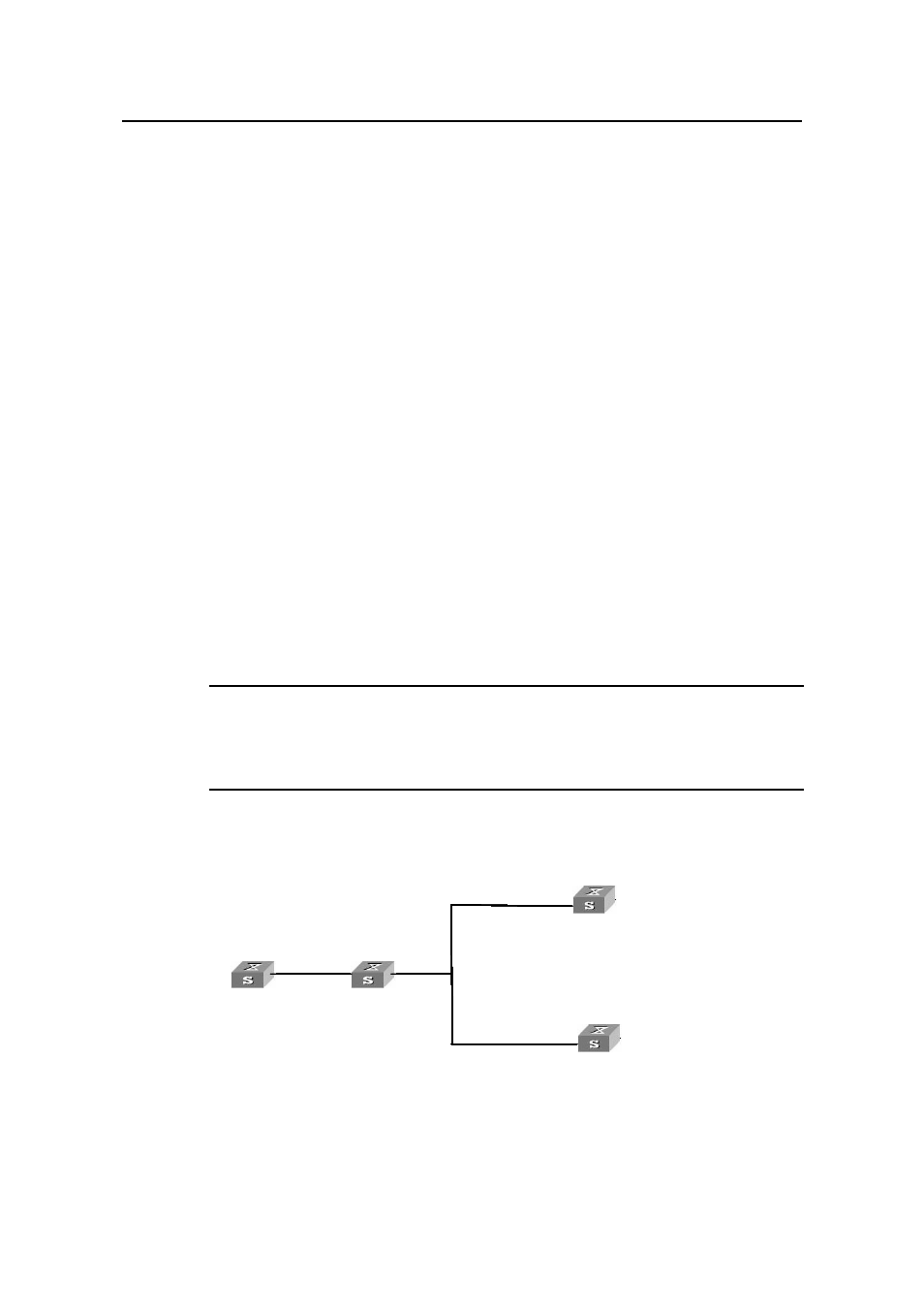
1.7.3 Configuring NTP Broadcast Mode
I. Network requirements
The local clock of H3C3 is set to the NTP master clock, with a stratum level of 2. NTP
packets are broadcast through Vlan-interface2.
Configure S3100-52P-1 and S3100-52P-2 to listen to broadcast packets through their
own Vlan-interface2.
Note:
This example assumes that H3C3 is a switch that supports the local clock being the
master clock.
II. Network diagram
H3C 3
3.0.1.31/24
3.0.1.32/24
rface 2
rface 2
H3C 4
1.0.1.31/24
Vlan-inte
Vlan-inte
S3100-52P-1
Vlan-interface 2
S3100-52P-2
H3C 3
3.0.1.31/24
3.0.1.32/24
rface 2
rface 2
H3C 4
1.0.1.31/24
Vlan-inte
Vlan-inte
S3100-52P-1
Vlan-interface 2
S3100-52P-2
Figure 1-8
Network diagram for the NTP broadcast mode configuration