Jumper settings, Jumper settings -10, P2 and p3 jumpers faceplate of adpcm card – Carrier Access Network Device Axxius 800 User Manual
Page 440: Quad ds1 adpcm card
13-10
Axxius 800 - Release 2.2
Quad DS1 ADPCM Card
Jumper Settings
Jumper Settings
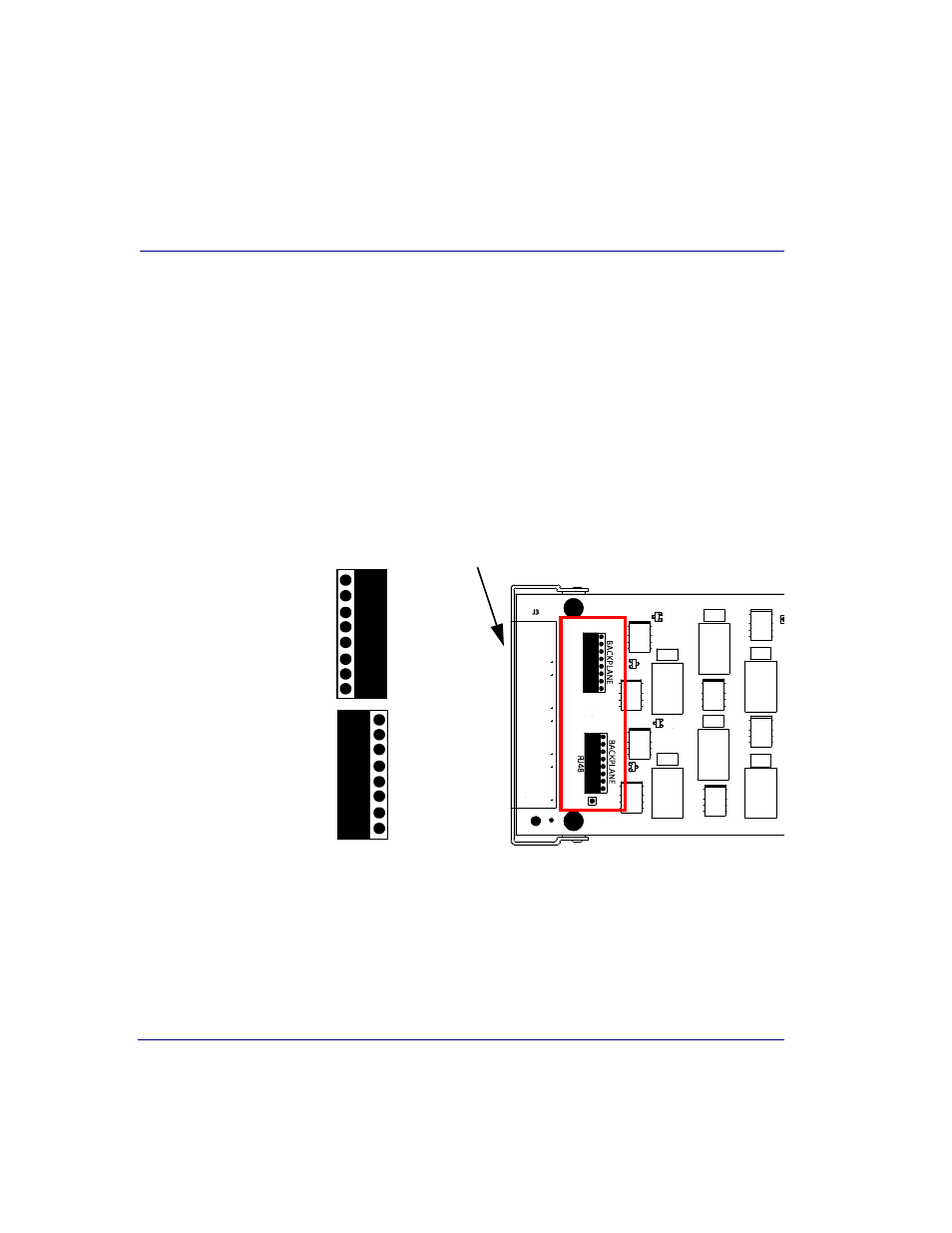
The P2 and P3 Jumpers are defaulted to RJ-48, which are the set of pins nearest the
connectors. In this position the DS1 signals (TX and RX) are routed to the RJ-48
connectors on the face of the card, see RJ-48 Connector on page 13-11 for pinout
information. To route the DS1 signals to the wire-wrap connector at the rear of the unit,
move all the jumpers to the "backplane" position (the two rightmost pins for each
signal). See Slot (1-8) Wire-Wrap Connectors on page 3-12 for more information on
these connectors.
P2 and P3 Jumpers
Faceplate of ADPCM card
P3
P2
3
24
1
22
3
24
1
BAC
KPLAN
E
BAC
K
P
LAN
E
1
22
24
3
1
22
24
3
RJ
4
8
RJ
4
8
Jumper set to
RJ-48 connector
on the front of
the card
Jumper set to
Wire-Wrap
connectors on the
back of the chassis