Example – Lenze E94ARNE Regenerative power supply User Manual
Page 158
9400 regenerative power supply module | Parameter setting
"CAN on board" system bus
Implemented CANopen objects
158
L
EDS94ARNExxxx EN 2.3 - 06/2014
Example
Parameter data channel 2 of the controller with node address 4 is to be activated.
For this purpose, bit 31 must be set to "0" (≡ "SDO is valid") in the subindexes 1 and 2 of
The two "write request" commands must be sent from the master to the nodes via the
basic SDO channel.
Calculation of the identifiers
Identifier (COB-ID) = basic identifier + node address (node ID)
Basic identifier SDO2 from the master to the drive: 1600 (0x640)
Identifier = 0x640 + 0x4 = 0x644
Basic identifier SDO2 from the drive to the master: 1472 (0x5C0)
Identifier = 0x5C0 + 0x4 = 0x5C4
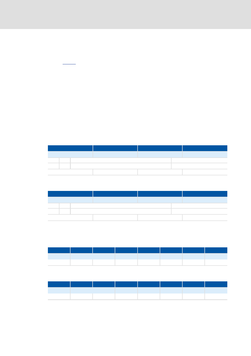
Resulting data (data 1 ... data 4)
[6-11] Assignment of the data telegram for subindex 1
[6-12] Assignment of the data telegram for subindex 2
Assignment of the user data
[6-13] Assignment of the user data for writing to subindex 1
[6-14] Assignment of the user data for writing to subindex 2
8th byte
7th byte
6th byte
5th byte
Data 4
Data 3
Data 2
Data 1
Bit 31
Bit 30
Bit 29 ... bit 11
Bit 10 ... bit 0
0
0
Extended identifier = 0
11-bit identifier = 0x644
0x00
0x00
0x06
0x44
8th byte
7th byte
6th byte
5th byte
Data 4
Data 3
Data 2
Data 1
Bit 31
Bit 30
Bit 29 ... bit 11
Bit 10 ... bit 0
0
0
Extended identifier = 0
11-bit identifier = 0x5C4
0x00
0x00
0x05
0xC4
1st byte
2nd byte
3rd byte
4th byte
5th byte
6th byte
7th byte
8th byte
Command
Index
Subindex
Data 1
Data 2
Data 3
Data 4
0x23
0x01
0x12
0x01
0x44
0x06
0x00
0x00
1st byte
2nd byte
3rd byte
4th byte
5th byte
6th byte
7th byte
8th byte
Command
Index
Subindex
Data 1
Data 2
Data 3
Data 4
0x23
0x01
0x12
0x02
0xC4
0x05
0x00
0x00