Yokogawa DAQWORX User Manual
Page 267
8-10
IM WX104-01E
SP No. Selecton Source
When specifying input contacts of SP No. settings, select the loop number of the SP
Number set to be switched. Activate or deactivate each loop number (CX1000: LOOP1
and LOOP2, CX2000: LOOP1 to LOOP6).
Pattern Number Selecton
(When [Program Control] for [Internal Loop] is ON)
With program control, you can select the range of pattern numbers when switching
program patterns through contact input. The pattern numbers are entered in binary
according to the number of relays required as shown in the following chart.
Pattern No.
No. of Relays
Assgned Relay(s)
1
1 (1 bit)
DI001
1–3
2 (2 bits)
DI001, DI002
1–7
3 (3 bits)
DI001–DI003
1–15
4 (4 bits)
DI001–DI004
1–30
5 (5 bits)
DI001–DI005
These are automatically registered under contact inputs according to the selected range
of program pattern numbers. [1–15] and [1–30] are active only if the number of program
patterns is 30 (/PG2).
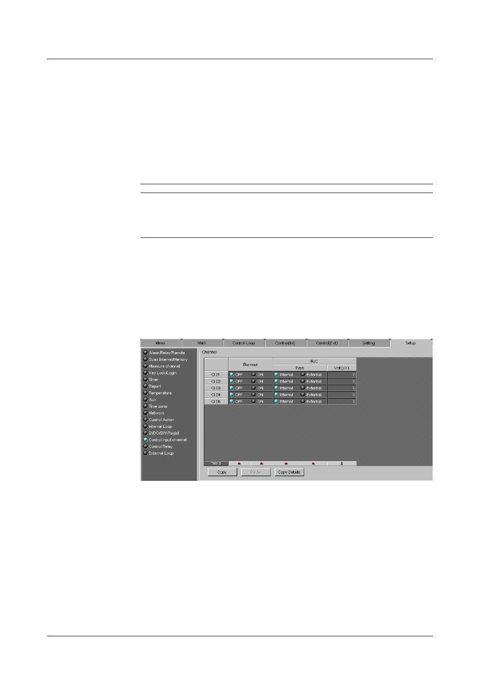
Control Input Channel (When PV/SP math s ON, CX Style Number S3 or Later)
When PV/SP math is ON (see Control Action), set the burnout and RJC (set under “Internal
Loop” when RV/SP math is OFF).
Burnout
Turn burnout ON/OFF for each control input channel.
RJC (Type, Volt (uV))
This is the reference junction compensation setting for thermocouple inputs. Set the
values for each control input channel. This setting is valid on the CX only for PV inputs
using thermocouples.
Select [Internal] or [External] for Type.
When [External] is selected, set [Volt (uV)] between –20000 uV and 20000 uV.
8.3 Control Functon Basc Settngs