Texas Instruments MSP430x1xx User Manual
Page 438
Flash Memory Access via JTAG and Software
C-26
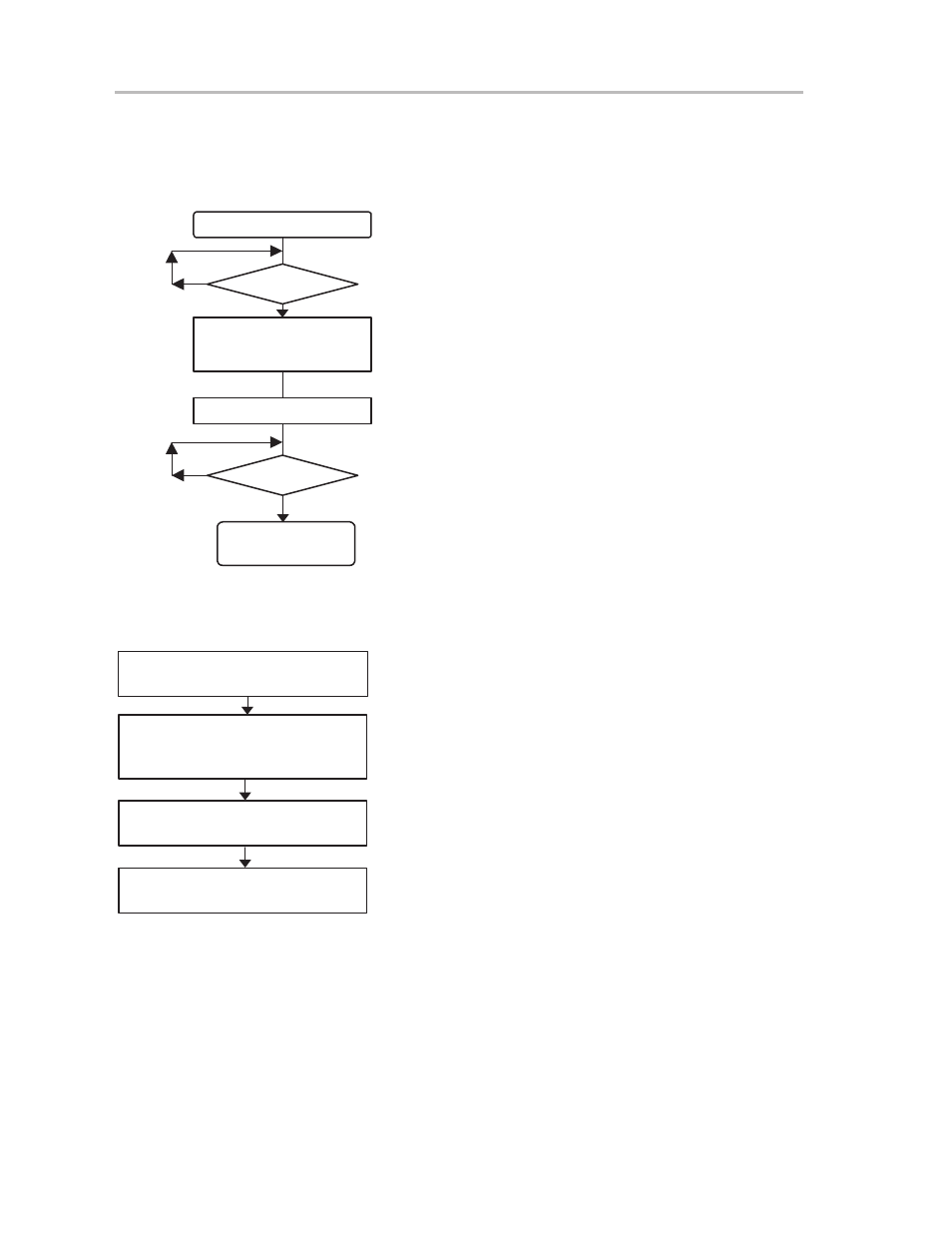
C.5.3.4 Example, Erase Flash Memory Segment or Module via Software Execution
Outside This Flash Module
The following sequence can be used to erase a segment, or mass-erase a
block of segments.
yes
BIC
#( Fwkey+Lock),&FCTL3 ;Reset Lock bit
Test_Busy1
Test_Busy2
XOR #(Fxkey+Lock),&FCTL3
Dummy Write
CLR &0F000h
BUSY = 1
yes
BUSY = 1
Erase or ‘Mass’ Erase
Segment Erase: Erase = 1
or
Mass Erase: MEras = 1
End of Erase or
‘Mass’ Erase
BIT
#BUSY,&FCTL3
JNZ
Test_Busy1
MOV
#(Fwkey+Erase),&FCTL1 ; select segment erase
BIT
#BUSY,&FCTL3
JNZ
Test_Busy2
C.5.3.5 Example, Erase Flash Memory Segment Module in the Same Flash Memory Module
via Software
Lock = 0,Eras=1 (or MEras=1)
Dummy Write to Flash Address in the
Target Segment
Disable all interrupt sources
and Watchdog
Restore or Enable Required
Interrupt Sources and Watchdog
MOV #(Fwkey+Eras),&FCTL1
;Enable Erase of Flash
CLR &0FA00h
;Dummy Write to Flash
;Erase Segment 2
XOR #(Fwkey+Lock),&FCTL3
: Change Lock bit to 1
; The erase bit Eras is automatically reset
Lock = 1
; Enable those interrupt sources that should be accepted
; Disable all possible interrupt sources and watchdog
; Program execution in information memory if MEras=1 (Eras=0)
C.5.3.6 Code for Write (Program), Erase, and Mass-Erase
Software that is active during write, erase, or mass-erase may not run in the
flash memory module where it is written or erased. Software that controls
write, erase, or mass-erase can be located in the flash memory module and
copied during execution into RAM. In this case the code should be written posi-
tion-independent, and should be loaded (for instance, to RAM) before it is
used. The algorithm runs in RAM during the programming sequence to avoid
conflict when the flash memory is written or erased.