1 watchdog timer register, Figure 9–2. watchdog timer control register, Table 9–1. wdtcnt taps – Texas Instruments MSP430x1xx User Manual
Page 135
The Watchdog Timer
9-3
Watchdog Timer
9.1.1
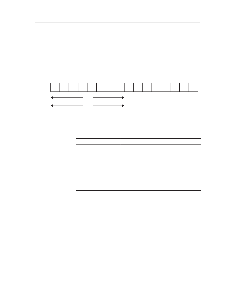
Watchdog Timer Register
The watchdog-timer counter (WDTCNT) is a 16-bit up-counter that is not
directly accessible by software. The WDTCNT is controlled through the
watchdog-timer control register (WDTCTL), shown in Figure 9–2, which is a
16-bit read/write register located at the low byte of word address 0120h. Any
read or write access must be done using word instructions with no suffix or
.w
suffix. In both operating modes (watchdog or timer), it is only possible to write
to WDTCTL using the correct password.
Figure 9–2. Watchdog Timer Control Register
HOLD
7
0
rw–0
WDTCTL
0120h
NMI
NMIES
TMSEL
SSEL
IS1
IS0
CNTCL
rw–0
rw–0
rw–0
r0(w)
rw–0
rw–0
rw–0
15
8
069h
05Ah
WDTCTL
read
WDTCTL
write
Bits 0, 1: Bits IS0 and IS1 select one of four taps from the WDTCNT, as
described in Table 9–1. Assuming f
crystal
= 32,768 Hz and
f
System
= 1 MHz, the following intervals are possible:
Table 9–1. WDTCNT Taps
SSEL
IS1
IS0
Interval [ms]
0
1
1
0.064
t
SMCLK
×
2
6
0
1
0
0.5
t
SMCLK
×
2
9
1
1
1
1.9
t
ACLK
×
2
6
0
0
1
8
t
SMCLK
×
2
13
1
1
0
16.0
t
ACLK
×
2
9
0
0
0
32
t
SMCLK
×
2
15
<– Value after PUC (reset)
1
0
1
250
t
ACLK
×
2
13
1
0
0
1000
t
ACLK
×
2
15
Bit 2:
The SSEL bit selects the clock source for WDTCNT.
SSEL = 0:
WDTCNT is clocked by SMCLK .
SSEL = 1:
WDTCNT is clocked by ACLK.
Bit 3:
Counter clear bit. In both operating modes, writing a 1 to this bit
restarts the WDTCNT at 00000h. The value read is not defined.
Bit 4:
The TMSEL bit selects the operating mode: watchdog or timer.
TMSEL = 0: Watchdog mode
TMSEL = 1: Interval-timer mode