1 system reset and initialization – Texas Instruments MSP430x1xx User Manual
Page 32
System Reset and Initialization
3-2
3.1
System Reset and Initialization
3.1.1
Introduction
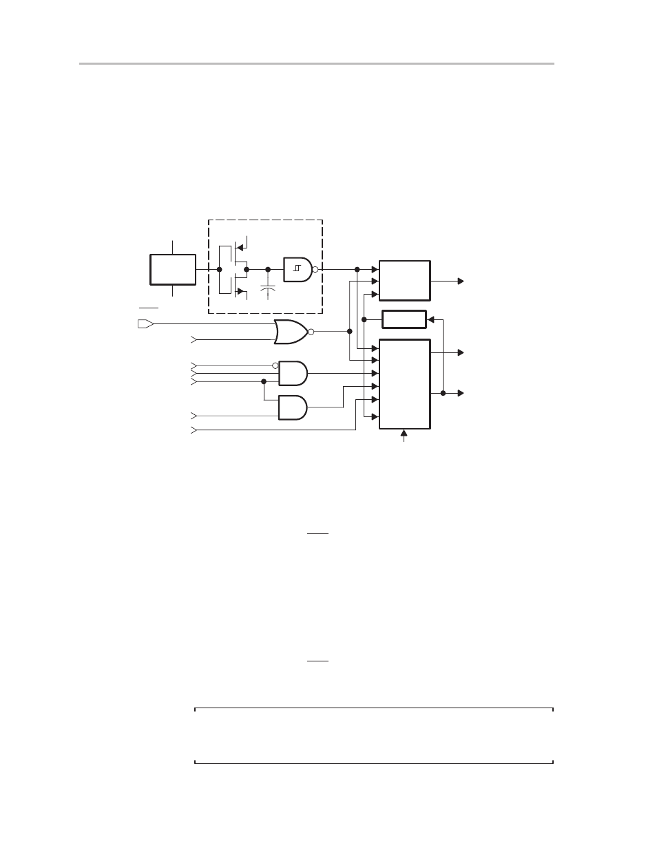
The MSP430 system reset circuitry (shown in Figure 3–1) sources two internal
reset signals: power-on reset (POR) and power-up clear (PUC). Different
events trigger these reset signals and different initial conditions exist
depending on which signal was generated.
Figure 3–1. Power-On Reset and Power-Up Clear Schematic
V
CC
POR
Detect
V
CC
POR
Latch
S
S
R
POR
Latch
S
S
R
Resetwd1
Resetwd2
S
S
Delay
RST/MNI
NMI(WDTCTL.5)
†
TIMSEL
†
WDTQn
†
WDTIFG
†
EQU
†
MCLK
POR Delay
POR
PUC_DCO
PUC
† From watchdog timer peripheral module
0 V
0 V
0 V
KEYV
S
(from flash module)
A POR is a device reset. It is only generated by the two following events:
-
Powering up the device
-
A low signal on the RST/NMI pin when configured in the reset mode
A PUC is always generated when a POR is generated, but a POR is not
generated by a PUC. The following events trigger a PUC:
-
A POR signal
-
Watchdog timer expiration (in watchdog mode only)
-
Watchdog timer security key violation
-
A low signal on the RST/NMI pin when configured in the NMI mode
-
A Flash memory security key violation
Note:
If desired, software can cause a PUC by simply writing to the watchdog timer
control register with an incorrect password.