Figure 13–17. usart clock phase and polarity, 3 receive control register urctl, Figure 13–18. receive control register urctl – Texas Instruments MSP430x1xx User Manual
Page 264
Control and Status Registers
13-18
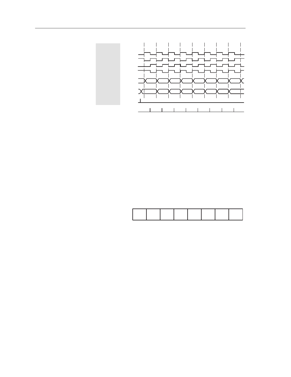
Figure 13–17. USART Clock Phase and Polarity
1
2
3
4
5
6
7
8
*
*
Cycle#
UCLK
UCLK
UCLK
UCLK
SIMO/
SOMI
SIMO/
SOMI
Data to
TXBUF
Receive
Sample Points
CKPL
0
1
0
1
x
x
CKPH
0
0
1
1
0
1
MSB
LSB
MSB
LSB
*Previous Data Bit
When operating with the CKPH bit set, the USART (synchronous mode)
makes the first bit of data available after the transmit shift register is loaded and
before the first edge of the UCLK. In this mode, data is latched on the first edge
of UCLK and transmitted on the second edge.
13.5.3 Receive Control Register URCTL
The receive control register (URCTL), shown in Figure 13–18, controls the
USART hardware associated with the receiver operation and holds error
conditions.
Figure 13–18. Receive Control Register URCTL
7
0
URCTL0, 072h
URCTL1, 07Ah
Unused
rw–0
FE
Undef.
OE
Unused
Undef.
Undef.
Undef.
rw–0
rw–0
rw–0
rw–0
rw–0
rw–0
rw–0
Bit 0:
Undefined, driven by USART hardware
Bit 1:
Undefined, driven by USART hardware
Bit 2:
Unused
Bit 3:
Unused
Bit 4:
Undefined, driven by USART hardware
Bit 5:
The overrun-error-flag bit (OE) is set when a character is
transferred to URXBUF before the previous character is read.
The previous character is overwritten and lost. OE is reset by a
SWRST, a system reset, by reading the URXBUF, or by an
instruction.
Bit 6:
Undefined, driven by USART hardware
Bit 7:
Frame error. The FE bit is set when four-pin mode is selected
and a bus conflict stops an active master by applying a negative