Texas Instruments MSP430x1xx User Manual
Page 278
Comparator_A in Applications
14-12
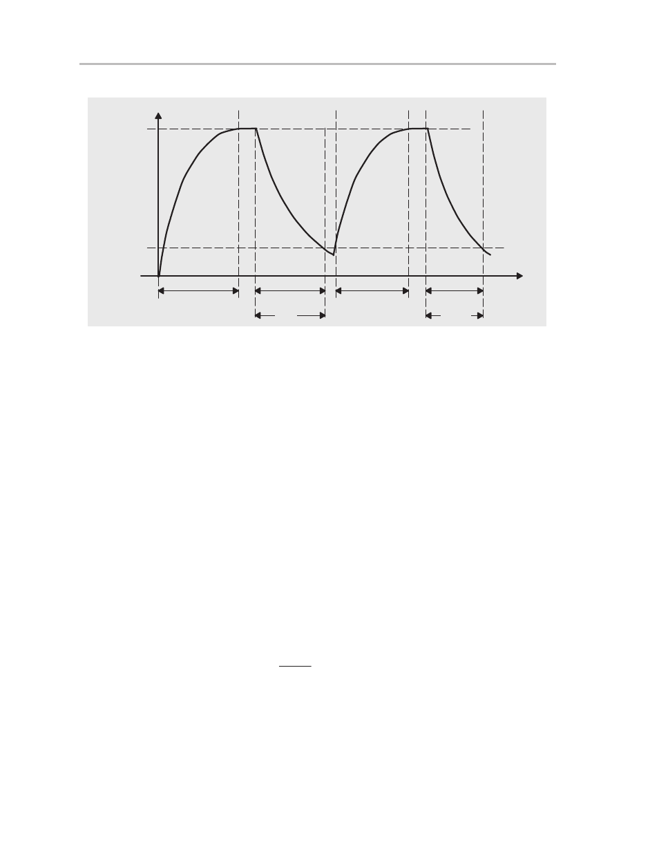
Figure 14–8. Timing for Temperature Measurement Systems
V
C
V
CC
0.25
×
V
CC
Phase I:
Charge-Up
Phase II:
Discharge C
Phase III:
Charge-Up
tref
Phase IV:
Discharge C
tmeas
t
R
meas
R
ref
MSP430 resources used to calculate the temperature sensed by R(meas):
Digital I/O:
-
Two digital outputs to charge and discharge the capacitor. Port pins are
set to provide a V
CC
output (charge a capacitor), reset to discharge a ca-
pacitor, and switched to high-impedance (including correct state of
CAPD.x bit) when not in use. One output discharges the capacitor via ref-
erence resistor R(ref), the other output discharges it via R(meas).
Comparator_A:
-
The – terminal is connected to a reference level, for example 0.25 x V
CC
.
-
The + terminal is connected to the positive terminal of the capacitor.
-
CAOUT or CAIFG utilized to measure the discharge time.
-
The output filter should be used to minimize multiple switching when the
voltages at the comparator inputs are close together.
If CAOUT is available as an input to a timer-capture register such as Timer_A,
the capacitor discharge time can be measured very precisely, without software
polling for a change of CAOUT, by using the timer capture function.
R
meas
+
R
ref
N
meas
N
ref
T
meas
+
ƒ
ǒ
R
meas
Ǔ