Texas Instruments MSP430x1xx User Manual
Page 256
Interrupt and Control Functions
13-10
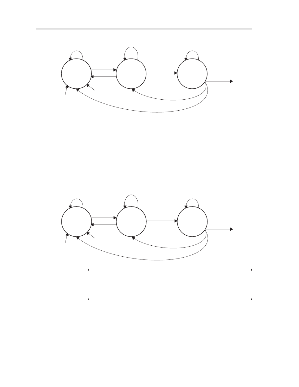
Figure 13–7. State Diagram of Receiver Enable Operation—MSP430 as Master
Idle State
(Receiver
Enabled)
Receive
Disable
Receiver
Collects
Character
USPIE = 0
No Data Written
to UTXBUF
Not Completed
USPIE = 1
USPIE = 0
USPIE = 1
Handle Interrupt
Conditions
Character
Received
USPIE = 1
USPIE = 0
SWRST
PUC
13.4.1.2 Receive/Transmit Enable Bit—MSP430 as Slave, Three-Pin Mode
The receive operation functions differently for three-pin and four-pin modes
when the MSP430 USART module is selected to be the SPI slave. In the
three-pin mode, shown in Figure 13–8, no external SPI receive-control signal
stops an active receive operation. A PUC signal, a software reset (SWRST),
or a receive/transmit enable (USPIE) signal can stop a receive operation and
reset the USART.
Figure 13–8. State Diagram of Receive/Transmit Enable—MSP430 as Slave, Three-Pin
Mode
Idle State
(Receive
Enabled)
Receive
Disable
Receiver
Collects
Character
USPIE = 0
No Clock at UCLK
Not Completed
USPIE = 1
USPIE = 0
USPIE = 1
Handle Interrupt
Conditions
Character
Received
USPIE = 1
USPIE = 0
SWRST
PUC
External Clock
Present
Note:
USPIE Re-enabled, SPI Mode
After the receiver is completely disabled, a reenabling of the receiver is asyn-
chronous to any data stream on the communication line. Synchronization to
the data stream is handled by the software protocol in three-pin SPI mode.
13.4.1.3 Receive/Transmit Enable Bit—MSP430 as Slave, Four-Pin Mode
In the four-pin mode, shown in Figure 13–9, the external SPI receive-control
signal applied to pin STE stops a started receive operation. A PUC signal, a
software reset (SWRST), or a receive/transmit enable (USPIE) can stop a
receive operation and reset the operation-control state machine. Whenever
the STE signal is set to high, the receive operation is halted.