Texas Instruments MSP430x1xx User Manual
Page 188
Timer Modes
11-12
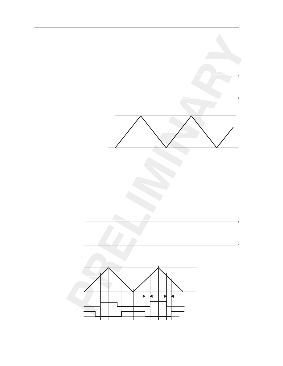
11.3.4 Timer—Up/Down Mode
The up/down mode is used if the timer period must be different from the
TBR
(max)
clock cycles, and if symmetrical pulse waveform generation is
needed. In up/down mode, the timer counts up to the content of compare latch
TBCL0, then back down to zero, as shown in Figure 11–12. The period is twice
the value in the TBCL0 latch.
Note:
If TBCL0 > TBR
(max),
the counter operates as if it were configured for
continuous mode. It will not count down from TBR
(max)
to zero.
Figure 11–12.Timer Up/Down Mode
0h
TBCL0
The up/down mode also supports applications that require dead times
between output signals. For example, to avoid overload conditions, two
outputs driving an H-bridge must never be in a high state simultaneously. In
the following example (see Figure 11–13), the t
dead
is:
t
dead
=
t
timer
×
(TBCL1 – TBCL3)=
With:
t
dead
Time during which both outputs need to be inactive
t
timer
Cycle time of the timer clock
TBCLx Content of compare latch x
Note:
The dead time is ensured by the ability to simultaneously load the compare
latches.
Figure 11–13.Output Unit in Up/Down Mode (II)
TBCL0
TBCL1
0h
TBIFG
EQU3
EQU1
Output Mode 6: PWM Toggle/Set
Output Mode 2: PWM Toggle/Reset
EQU0
EQU3
EQU1
EQU3
Dead Time
EQU1
EQU3
TBIFG
EQU1
EQU0
Interrupt Events
TBCL3
TBR
(max)