Figure 10–13. output unit in up/down mode (ii), Figure 10–14. timer up/down direction control – Texas Instruments MSP430x1xx User Manual
Page 151
Timer Modes
10-11
Timer_A
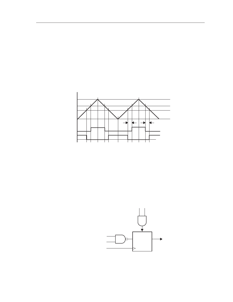
The up/down mode also supports applications that require dead times
between output signals. For example, to avoid overload conditions, two
outputs driving an H-bridge must never be in a high state simultaneously. In
the following example (see Figure 10–13), the t
dead
is:
t
dead
=
t
timer
×
(CCR1 – CCR3)=
With:
t
dead
Time during which both outputs need to be inactive
t
timer
Cycle time of the timer clock
CCRx Content of capture/compare register x
Figure 10–13. Output Unit in Up/Down Mode (II)
0FFFFh
CCR0
CCR1
0h
TAIFG
EQU3
EQU1
Output Mode 6: PWM Toggle/Set
Output Mode 2: PWM Toggle/Reset
EQU0
EQU3
EQU1
EQU3
Dead Time
EQU1
EQU3
TAIFG
EQU1
EQU0
Interrupt Events
CCR3
The count direction is always latched with a flip-flop (Figure 10–14). This is
useful because it allows the user to stop the timer and then restart it in the same
direction it was counting before it was stopped. For example, if the timer was
counting down when the MCx bits were reset, then it will continue counting in
the down direction if it is restarted in up/down mode. If this is not desired, the
CLR bit in the TACTL register must be used to clear the direction. Note that the
CLR bit affects other setup conditions of the timer. Refer to Section 10.6 for a
discussion of the Timer_A registers.
Figure 10–14. Timer Up/Down Direction Control
Set
D
Q
Reset
POR
CLR
in TACTL
Up/Down For
16-Bit Timer TAR
Low: Down Direction
High: Up Direction
Up/Down Mode
TAR => CCR0
Timer Clock