Texas Instruments MSP430x1xx User Manual
Page 305
Conversion Modes
15-15
ADC12
An example showing a sequence of conversions is shown and flow-charted
in Figures 15–9 and 15–10. The example shows the sequence a0, a5, a7, a0,
a0, a3, and uses ADC12MEM6 for storing the first conversion results. The set-
up of each conversion in the sequence is:
-
a0, using reference voltages V
R+
= AV
CC
and V
R–
= AV
SS
-
a5, using reference voltages V
R+
at V
REF+
and V
R–
= AV
SS
-
a7, using reference voltages V
R+
at V
REF+
and V
R–
= Ve
REF–
/ V
REF–
-
a0, using reference voltages V
R+
= AV
CC
and V
R–
= AV
SS
-
a0, using reference voltages V
R+
= AV
CC
and V
R–
= AV
SS
-
a3, using reference voltages V
R+
= AV
CC
and V
R–
= Ve
REF–
/ V
REF–
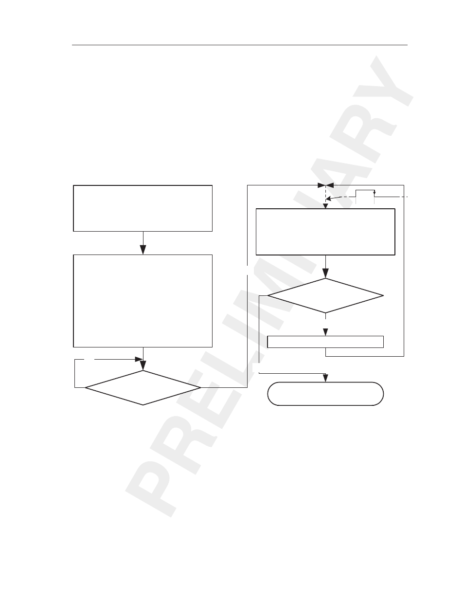
Figure 15–9. Sequence-of-Channels Mode Flow
Define basic conversion conditions
via control registers ADC12CTL0/1
x = 6 ( CStartAdd = 6
)
Define reference and channel
in control registers ADC12MCTL6x
ADC12MCTL6 = 0h
ADC12MCTL7 = 015h
ADC12MCTL8 = 057h
ADC12MCTL9 = 0h
ADC12MCTL10 = 0h
ADC12MCTL11 = 0C3h
Sample and convert channel
using ADC12MCTLx, and store
conversion result in ADC12MEMx
ENC 0
→
1
Yes
No
EOS in ADC12MCTLx = 1
Yes
No
Stop conversion sequence
x = x + 1
Sample Conversion
SAMPCON