Figure 11–32.vector word register – Texas Instruments MSP430x1xx User Manual
Page 212
Timer_B Registers
11-36
11.6.4.2 Vector Word, TBIFG, CCIFG1 to CCIFGx Flags
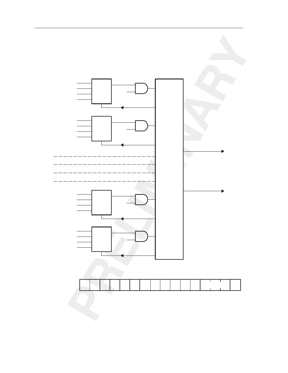
The CCIFGx (other than CCIFG0) and TBIFG interrupt flags are prioritized and
combined to source a single interrupt as shown in Figure 11–31. The interrupt
vector register TBIV (shown in Figure 11–32) is used to determine which flag
requested an interrupt.
Figure 11–31.Schematic of Capture/Compare Interrupt Vector Word
S
S
Sel
R
CCI1
EQ1
CMP1
Timer Clock
IRACC
CCIE1
CCIFG1
S
S
Sel
R
CCI2
EQ2
CMP2
Timer Clock
IRACC
CCIE2
CCIFG2
S
S
Sel
R
CCI6
EQ6
CMP6
Timer Clock
IRACC
CCIE6
CCIFG6
S
S
Sel
R
TBR
(MAX)
Timer = TBCL0
XXX
Timer Clock
IRACC
TBIE
TBIFG
Priority and
Vector Word
Generator
Interrupt_Service_Request
Interrupt_Vector_Address
Module 3
Module 4
Module 5
Figure 11–32.Vector Word Register
r0
15
0
TBIV
11Eh
0
r0
r0
r0
r0
r0
r0
r0
r0
r0
r0
r0
r0
0
0
0
0
0
0
0
0
0
0
Interrupt Vector
0
r-(0) r-(0) r-(0)
0
The flag with the highest priority generates a number from 2 to 14 in the TBIV
register as shown in Table 11–9. (If the value of the TBIV register is 0, no
interrupt is pending.) This number can be added to the program counter to
automatically enter the appropriate software routine without the need for
reading and evaluating the interrupt vector. The software example in section
11.6.4.3 shows this technique.