1 operation of the dco modulator, Figure 7–13. operation of the dco modulator – Texas Instruments MSP430x1xx User Manual
Page 112
Digitally-Controlled Oscillator (DCO)
7-12
7.3.1
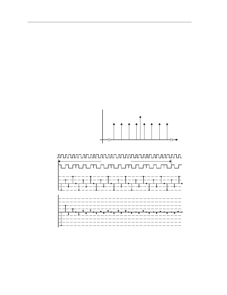
Operation of the DCO Modulator
The modulator is intended to reduce a long accumulating period variation by
mixing adjacent DCO periods. On average, a longer period variation can be
minimized by mixing DCO periods. The modulator accumulates a period of 32
DCOCLK clock cycles. The MOD control bits define the mixing ratio of the
DCO+1 period. The remaining 32-MOD time slots use the DCO period. If the
modulation constant is 0, the DCO data in the control register defines the peri-
od. The following formula defines the accumulating periods:
t =(32– MOD)
×
t
DCO
+ MOD
×
t
DCO+1
The modulator selects f
dco
or f
dco
+1 individually for each DCO cycle. This is
the highest possible rate that can be modulated between two discrete
frequency steps. The following example illustrates the main operation of the
modulator.
Figure 7–13. Operation of the DCO Modulator
DCOCLK
f0
f1
f2
f3
f4
f5
f6
f7
Frequency Selected
Frequency
1000 kHz
943 kHz
1042 kHz
Cycle Time
1000 ns
1060 ns
960 ns
Selected:
f3:
f4:
MOD = 19
Modulation Period
1
0
DCO
(ns)
40
20
0
–20
–40
(%)
4
3
2
1
0
–1
–2
–3
–4
Error of
Σ
tperiod
Error of
Σ
tperiod