Texas Instruments MSP430x1xx User Manual
Page 182
Timer_B Operation
11-6
Table 11–1. Timer Modes
Mode Control
MC1
MC0
Mode
Description
0
0
Stop
The timer is halted.
0
1
Up
The timer counts upward until its value is equal to
the value of compare latch TBCL0.
Note: If TBCL0 > TBR
(max),
the counter counts to
zero with the next rising edge of timer clock.
1
0
Continuous
The timer counts upward continuously.
The maximum value of TBR [TBR
(max)
] is:
0FFFFh for 16-bit configuration
00FFFh for 12-bit configuration
003FFh for 10-bit configuration
000FFh for 8-bit configuration
1
1
Up/Down
The timer counts up until the timer value is equal
to compare latch 0 and then it counts down to zero.
Note: If TBCL0 > TBR
(max),
the counter operates
as if it were configured for continuous mode. It will
not count down from TBR
(max)
to zero.
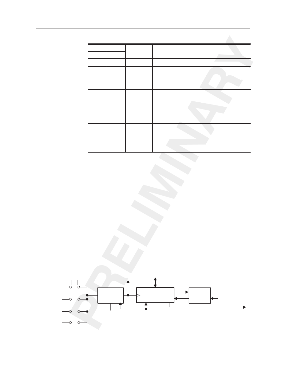
11.2.3 Clock Source Select and Divider
The timer clock can be sourced from internal clocks (i.e. ACLK, MCLK or
SMCLK) or from an external source (TBCLK) as shown in Figure 11–3. The
clock source is selectable with the SSEL0 and SSEL1 bits in the TBCTL regis-
ter. It is important to note, that when changing the clock source for the timer,
errant timings can occur. For this reason stopping the timer before changing
the clock source is recommended.
The selected clock source may be passed directly to the timer or divided by
2,4, or 8, as shown in Figure 11–4. The ID0 and ID1 bits in the TBCTL register
select the clock division. Note that the input divider is reset by a POR signal
or by setting the CLR bit in the TBCTL register (see chapter 3,
System Resets,
Interrupts, and Operating Modes, for more information on the POR signal).
Otherwise, the input divider remains unchanged when the timer is modified.
The state of the input divider is invisible to software.
Figure 11–3. Schematic of 16-Bit Timer
Input
Divider
CLK
16-Bit Timer
†
SSEL0
SSEL1
TBCLK
ACLK
SMCLK
0
1
2
3
RC
INCLK
ID1
ID0
0
15
Data
Timer Clock
POR/CLR
Mode
Control
MC1
MC0
Equ0
Carry/Zero
Set_TBIFG
0
0
1
1
0
1
0
1
Pass
1/2
1/4
1/8
0
0
1
1
0
1
0
1
Stop Mode
Up Mode
Continuous Mode
Up/Down Mode
† Length is selectable for 8-, 10-, 12-, or 16-bit operation.