Texas Instruments MSP430x1xx User Manual
Page 107
LFXT1 and XT2 Oscillators
7-7
Basic Clock Module
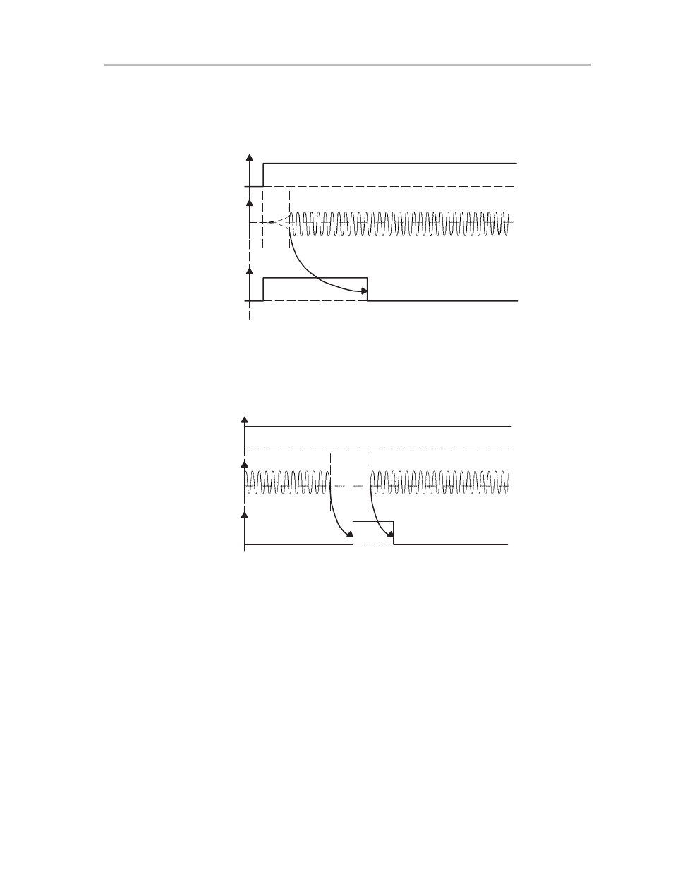
After applying V
CC
the oscillator fault signal (XT_OscFault) becomes active.
The XT_OscFault signal becomes inactive when XT2CLK and/or LFXT1CLK
begin oscillating, which takes approximately 50 clock cycles (at 1 MHz).
Figure 7–6. Oscillator-Fault Signal
V
CC
XT2CLK
LFXT1CLK
XT_OscFault
Oscillator
Start-Up
XT_OscFault becomes active after XT2CLK and/or LFXT1CLK stop oscillat-
ing. The delay associated with the XT_OscFault signal is approximately 50
clock cycles (at 1 MHz).
Figure 7–7. Oscillator Fault in Oscillator Error Condition
V
CC
XT2CLK
LFXT1CLK
XT_OscFault
Oscillator
Error
The oscillator-fault signal returns to a logic low if the oscillator starts operating
again. The delay is typically 50 clock cycles (at 1 MHz).
When an XT oscillator has stopped and is then restarted, the oscillator fault
signal (XT_OscFault) remains active until the oscillator starts operating, and
becomes inactive after a delay of typically 50 clock cycles at (1 MHz).