Texas Instruments MSP430x1xx User Manual
Page 183
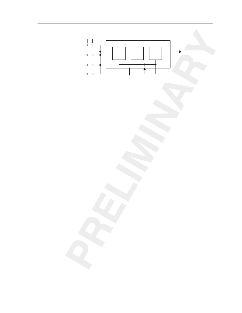
Timer_B Operation
11-7
Timer_B
Figure 11–4. Schematic of Clock Source Select and Input Divider
T
Q
16-Bit Timer Clock
ID1
C
T
Q
C
T
Q
C
ID0
POR
CLR
0
0
1
1
0
1
0
1
Pass
1/2
1/4
1/8
Input Divider
SSEL0
SSEL1
TBCLK
ACLK
SMCLK
0
1
2
3
INCLK
11.2.4 Starting the Timer
The timer may be started or restarted in a variety of ways:
-
Release Halt Mode: The timer
counts in the selected direction when a
timer mode other than stop mode is selected with the MCx bits.
-
Halted by TBCL0 = 0, restarted by TBCL0 > 0 when the mode is either up
or up/down: When the timer mode is selected to be either up or up/down,
the timer may be stopped by loading 0 in compare latch 0 (TBCL0) via cap-
ture/compare register (CCR0). The timer may then be restarted by loading
a nonzero value to TBCL0. In this scenario, the timer starts incrementing
in the up direction from zero.
-
Setting the CLR bit in TBCTL register: Setting the CLR bit in the TBCTL
register clears the timer value and input clock divider value. The timer
increments upward from zero with the next clock cycle as long as
stop-mode is not selected with the MCx bits.
-
TBR is loaded with 0: When the counter (TBR register) is loaded with zero
with a software instruction the timer increments upward from zero with the
next clock cycle as long as stop-mode is not selected with the MCx bits.