2 timer_b register tbr, Figure 11–28.tbr register, 3 capture/compare control register cctlx – Texas Instruments MSP430x1xx User Manual
Page 208
Timer_B Registers
11-32
Note:
Changing Timer_B Control Bits
If the timer operation is modified by the control bits in the TBCTL register, the
timer should be halted during this modification. Critical modifications are the
input select bits, input divider bits, and the timer clear bit. Asynchronous
clocks, input clock, and system clock can result in race conditions where the
timer reacts unpredictably.
The recommended instruction flow is:
1) Modify the control register and stop the timer with one instruction.
2) Start the timer operation.
For example:
MOV #0286h,&TBCTL ; ACLK/8, timer stopped, timer cleared
BIS #10h,&TBCTL ; Start timer with up mode
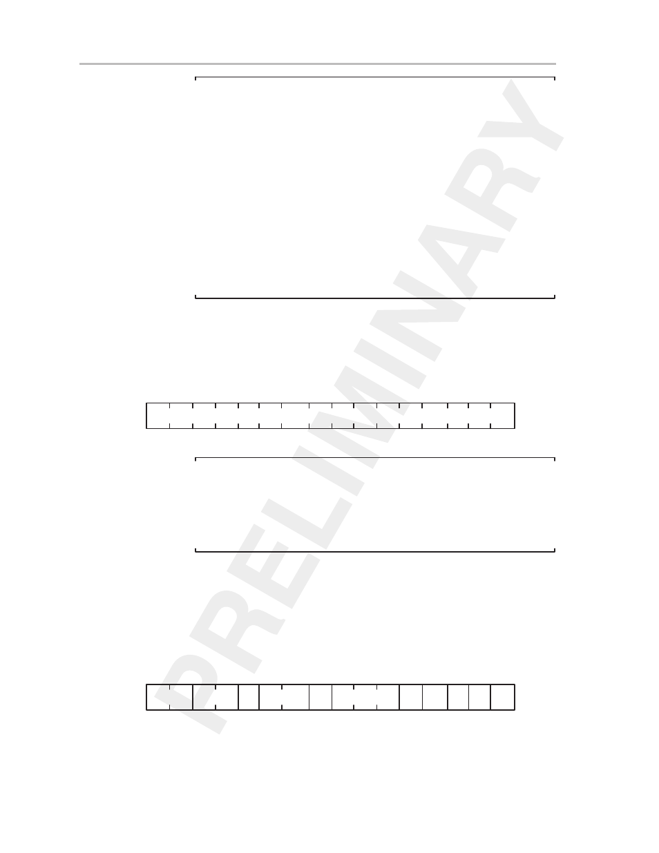
11.6.2 Timer_B Register TBR
The TBR register is the value of the timer.
Figure 11–28.TBR Register
rw-(0)
15
0
TBR
190h
Timer Value
rw-(0) rw-(0) rw-(0)rw-(0) rw-(0) rw-(0)rw-(0)rw-(0)rw-(0)rw-(0) rw-(0)
rw-(0)rw-(0) rw-(0)
rw-(0)
Note:
Modifying Timer_B Register TBR
When ACLK, SMCLK, or the external clock TBCLK or INCLK is selected for
the timer clock, any write to timer register TBR should occur while the timer
is not operating; otherwise, the results may be unpredictable. In this case,
the timer clock is asynchronous to the CPU clock MCLK and critical race
conditions exist.
11.6.3 Capture/Compare Control Register CCTLx
Each capture/compare block has its own control word CCTLx, shown in
Figure 11–29. The POR signal resets all bits of CCTLx; the PUC signal does
not affect these bits.
Figure 11–29.Capture/Compare Control Register CCTLx
rw-(0)
15
0
Input
Select
CCIE
OUT COV CCIFG
CCTLx
182h to 19Ah
Capture
Mode
SCS
CLLD
CAP
OUTMODx
CCI
r
rw-(0) rw-(0) rw-(0)rw-(0) rw-(0) rw-(0) rw-(0)rw-(0)rw-(0)rw-(0) rw-(0)
rw-(0)rw-(0) rw-(0)