6 measuring the offset voltage of comparator_a – Texas Instruments MSP430x1xx User Manual
Page 286
Comparator_A in Applications
14-20
14.4.6 Measuring the Offset Voltage of Comparator_A
The input offset voltage of the comparator varies with each device and also
with temperature, supply voltage, and input voltage. If the input voltage is
stable (
reference voltage), it will not influence the offset voltage significantly.
To increase the precision of voltage measurements, the comparator offset
voltage can be measured by the following steps. To simply compensate for the
offset without measuring it, see section 14.4.7
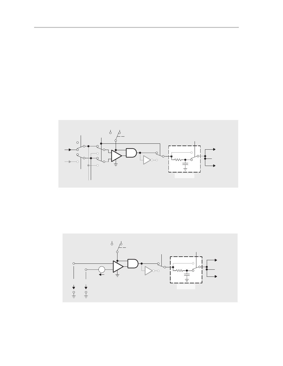
First, execute a conversion with CAEX = 0. V
CA0
is applied to the + terminal
of the comparator, and V
ref
is applied to the – terminal of the comparator as
shown in Figure 14–18.
Figure 14–18. Measuring the Offset Voltage of the Comparator, CAEX = 0
_
+
0
1
CAF
Set
CAIFG
τ
∼
2
µ
s
0
1
0
1
0
1
0
1
CA0
CA1
0
1
P2CA0
P2CA1
CAEX
Vref
CAON
VCC
0 V
1
0
e.g.
Capture
Input of
Timer_A
CAOUT to
External Pin
The V
offset
in this configuration is in series with V
ref
as shown in Figure 14–19.
V
CA0
=
V
ref
+
V
offset
Figure 14–19. Offset Voltage of the Comparator, CAEX = 0
_
+
0
1
CAF
Set
CAIFG
τ
∼
2
µ
s
0
1
CAEX
Voffset
VCA0
Vref
CAON
VCC
0 V
1
0
e.g.
Capture
Input of
Timer_A
CAOUT to
External Pin
Next, execute a conversion with CAEX = 1. V
CA0
is applied to the – terminal
of the comparator, and V
ref
is applied to the + terminal of the comparator as
shown in Figure 14–20.