1 usart control register, Figure 13–15. usart control register, 2 transmit control register utctl – Texas Instruments MSP430x1xx User Manual
Page 262: Figure 13–16. transmit control register utctl
Control and Status Registers
13-16
13.5.1 USART Control Register
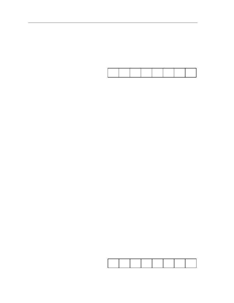
The information stored in the control register, shown in Figure 13–15,
determines the basic operation of the USART module. The register bits select
the communication mode and the number of bits per character. All bits should
be programmed to the desired mode before resetting the SWRST bit.
Figure 13–15. USART Control Register
7
0
rw–0
UCTL0, 070h
UCTL1, 078h
CHAR
SWRST
Listen
rw–0
rw–0
rw–0
rw–0
rw–0
rw–1
Unused
SYNC
rw–0
MM
Unused Unused
Bit 0:
The USART state machines and operating flags are initialized
to the reset condition (URXIFG=USPIE=0, UTXIFG=1) if the
software reset bit is set. Until the SWRST bit is reset, all affected
logic is held in the reset state. This implies that after a system
reset the USART must be reenabled by resetting this bit.
Bit 1:
Master mode is selected when the MM bit is set. The USART
module slave mode is selected when the MM bit is reset.
Bit 2:
Peripheral module mode select
The SYNC bit sets the function of the USART peripheral-
interface module. Some of the USART control bits have different
functions in UART and SPI modes.
SYNC = 0: UART function is selected
SYNC = 1: SPI function is selected
Bit 3:
The listen bit determines the transmitted data to feed back
internally to the receiver. This is commonly called loopback
mode.
Bit 4:
Character length
This register bit sets the length of the character to be transmitted
as either seven or eight bits.
CHAR = 0: 7-bit data
CHAR = 1: 8-bit data
Bit 5:
Unused
Bit 6:
Unused
Bit 7:
Unused
13.5.2 Transmit Control Register UTCTL
The transmit control register (UTCTL), shown in Figure 13–16, controls the
USART hardware associated with transmitter operations.
Figure 13–16. Transmit Control Register UTCTL
7
0
rw–0
UTCTL0, 071h
UTCTL1, 079h
SSEL0
TXEPT
Unused
rw–0
rw–0
rw–0
rw–0
rw–0
rw–1
CKPH
rw–0
STC
CKPL
SSEL1
Unused