Figure 11–10.continuous mode flag setting – Texas Instruments MSP430x1xx User Manual
Page 187
Timer Modes
11-11
Timer_B
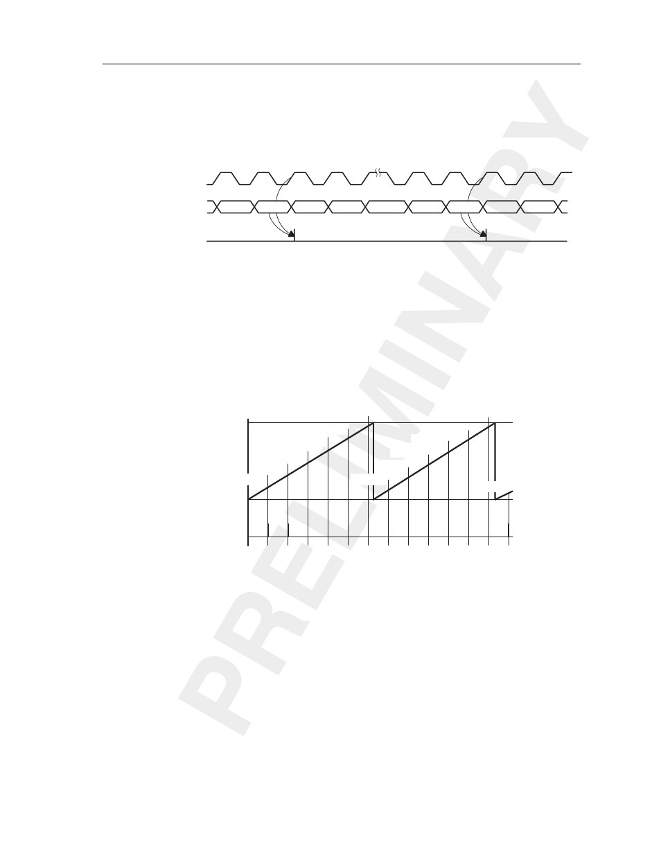
The TBIFG flag is set when the timer
counts from TBR
(max)
to zero. The
interrupt flag is set independently of the corresponding interrupt enable bit, as
shown in Figure 11–10. An interrupt is requested if the corresponding interrupt
enable bit and the GIE bit are set.
Figure 11–10.Continuous Mode Flag Setting
TBR(max)–1
TBR(max)
0h
1h
0h
1h
Timer
Clock
Timer
Set Interrupt
Flag TBIFG
TBR(max)
TBR(max)–1
11.3.3.1 Timer—Use of the Continuous Mode
The continuous mode can be used to generate time intervals for the
application software. Each time an interval is completed, an interrupt can be
generated. In the interrupt service routine of this event, the time until the next
event is added to capture/compare register CCRx (and subsequently compare
latch TBCLx) as shown in Figure 11–11. Up to seven independent time events
can be generated using all seven capture/compare blocks.
Figure 11–11. Output Unit in Continuous Mode for Time Intervals
∆
t
TBCL0a
TBCL0b
TBCL0c
TBCL0d
TBCL0e
TBCL0f
TBCL0h
TBCL0i
TBCL0j
TBCL0k
TBCL0l
∆
t
∆
t
∆
t
∆
t
∆
t
∆
t
∆
t
∆
t
∆
t
∆
t
∆
t
TBR
(max)
0h
Interrupt Events
TBCL0g
TBCL0m
Time intervals can be produced with other modes as well, where capture/
compare block 0 is used to determine the period. Their handling is more
complex since the sum of the old CCRx data and the new period can be higher
than the TBCL0 value. When the sum CCRxold plus
∆
t is greater than the
TBCL0 data, the old CCR0 value must be subtracted to obtain the correct time
interval.