Texas Instruments MSP430x1xx User Manual
Page 316
Sampling
15-26
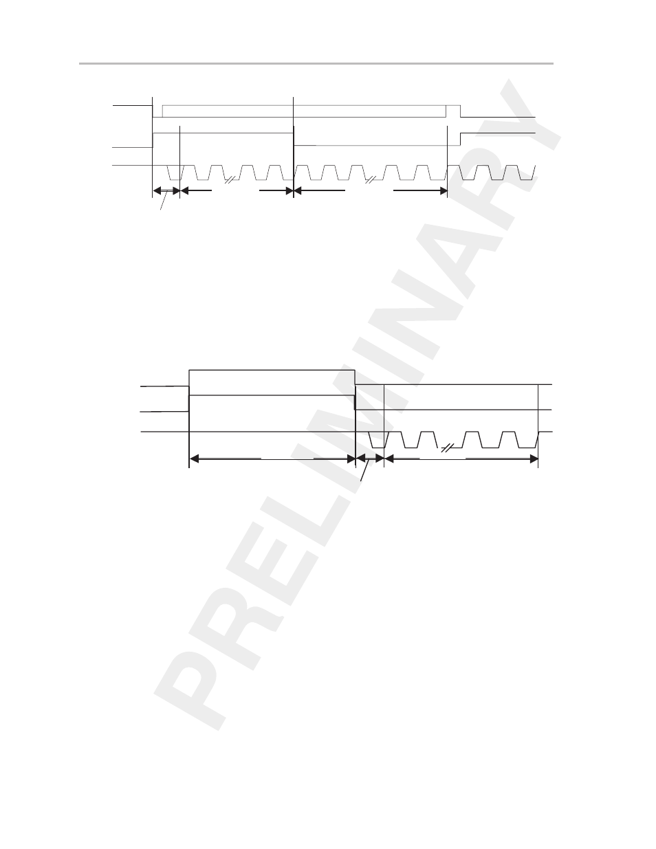
Figure 15–19. Pulse-Sample Mode Example Timing
Timer_B.OUT0
tsync
tsample
tconvert
SAMPCON
ADC12CLK
Additional edges are ignored until after conversion completes
Next sync and sample
15.7.3.2 Extended-Sample Mode
In extended-sample mode, the input signal selected by the SHS bits is used
to control the sampling (SAMPCON signal) directly. The internal sampling tim-
er is not used. As shown in Figure 15–20, the sampling period is active while
SAMPCON is high. Hold mode is active when SAMPCON is low. The conver-
sion starts with the falling edge of SAMPCON after a synchronization time
t
sync
. The conversion takes 13
×
ADC12CLK (t
convert
).
Figure 15–20. Conversion Timing for Extended-Sample Mode
t sync
t sample
t convert
SAMPCON
ADC12CLK
Sample-Input Signal
The extended-sample mode allows total control of the sampling period and the
start of a conversion. The extended-sample mode is useful in applications that
require an extended sampling period to accommodate different input-source
impedances, or in applications where the maximum sampling period supplied
by the internal sampling timer is insufficient.
An example of the extended-sample-mode configuration is shown in
Figure 15–21. The selected input signal source is Timer_B.OUT0. The timing
for the example is shown in Figure 15–22.