Texas Instruments MSP430x1xx User Manual
Page 169
Timer_A Registers
10-29
Timer_A
Bits 14, 15:
Capture mode bits:
Table 10–8 describes the capture mode selections.
Table 10–8.Capture/Compare Control Register Capture Mode
Bit
Value
Capture Mode
Description
0
Disabled
The capture mode is disabled.
1
Positive Edge
Capture is done with rising edge.
2
Negative Edge
Capture is done with falling edge.
3
Both Edges
Capture is done with both rising and falling edges.
Note:
Simultaneous Capture and Capture Mode Selection
Captures must not be performed simultaneously with switching from
compare to capture mode. Otherwise, the result in the capture/compare reg-
ister will be unpredictable.
The recommended instruction flow is:
1) Modify the control register to switch from compare to capture.
2) Capture
For example:
BIS #CAP,&CCTL2
; Select capture with register CCR2
XOR #CCIS1,&CCTL2
; Software capture:
CCIS0 = 0
;
Capture mode = 3
10.6.4 Timer_A Interrupt Vector Register
Two interrupt vectors are associated with the 16-bit Timer_A module:
-
CCR0 interrupt vector (highest priority)
-
TAIV interrupt vector for flags CCIFG1–CCIFGx and TAIFG.
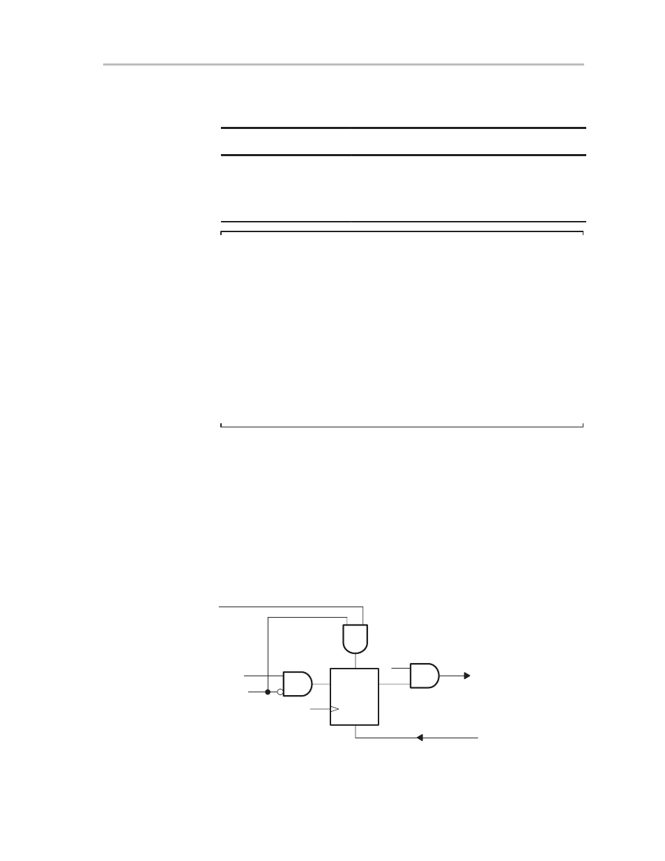
10.6.4.1 CCR0 Interrupt Vector
The interrupt flag associated with capture/compare register CCR0, as shown
in Figure 10–30, is set if the timer value is equal to the compare register value.
Figure 10–30. Capture/Compare Interrupt Flag
D
Q
Reset
Set
CCIE0
Timer Clock
CAP
EQ0
CCR0 = Timer
Capture
IRQ, Interrupt_Service_Requested
IRACC, Interrupt_Request_Accepted
Capture/compare register 0 has the highest Timer_A interrupt priority, and
uses its own interrupt vector.