4 capture/compare blocks, Figure 11–17.capture/compare blocks – Texas Instruments MSP430x1xx User Manual
Page 191
Timer Modes
11-15
Timer_B
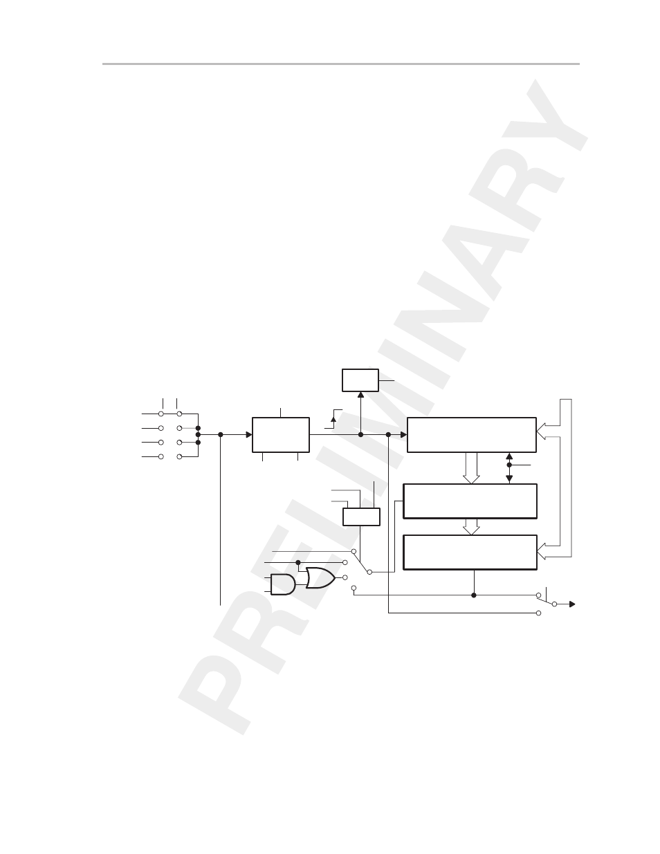
11.4 Capture/Compare Blocks
Seven identical capture/compare blocks (shown in Figure 11–17) provide
flexible control for real-time processing. Any one of the blocks may be used
to capture the timer data at an applied event, or to generate time intervals.
Each time a capture occurs or a time interval is completed, interrupts can be
generated from the applicable capture/compare register. The mode bit CAPx,
in control word CCTLx, selects the compare or capture operation and the
capture mode bits CCMx1 and CCMx0 in control word CCTLx define the
conditions under which the capture function is performed.
Both the interrupt enable bit CCIEx and the interrupt flag CCIFGx are used for
capture and compare modes. CCIEx enables the corresponding interrupt.
CCIFGx is set on a capture or compare event.
The capture inputs CCIxA and CCIxB are connected to external pins or internal
signals. Different MSP430 devices may have different signals connected to
CCIxA and CCIxB. The data sheet should always be consulted to determine
the Timer_B connections for a particular device.
Figure 11–17.Capture/Compare Blocks
Capture
Mode
CCISx0
CCISx1
CCIxA
CCIxB
GND
0
1
2
3
VCC
CCMx1
CCMx0
Capture/Compare Register
CCRx
Set_CCIFGx
Logic
Capture
15
0
Comparator x
0
1
CAPx
CCIx
COVx
Overflow x
CAPx
EQUx
CCMx1 CCMx0
0
0
1
1
0
1
0
1
Disabled
Positive Edge
Negative Edge
Both Edges
Compare Latch TBCLx
15
0
Load
POR
CLLD1
CLLD0
CAP
High
Zero
EQU0
Up/Down
Reset
Reset