6 timer_a registers – Texas Instruments MSP430x1xx User Manual
Page 164
Timer_A Registers
10-24
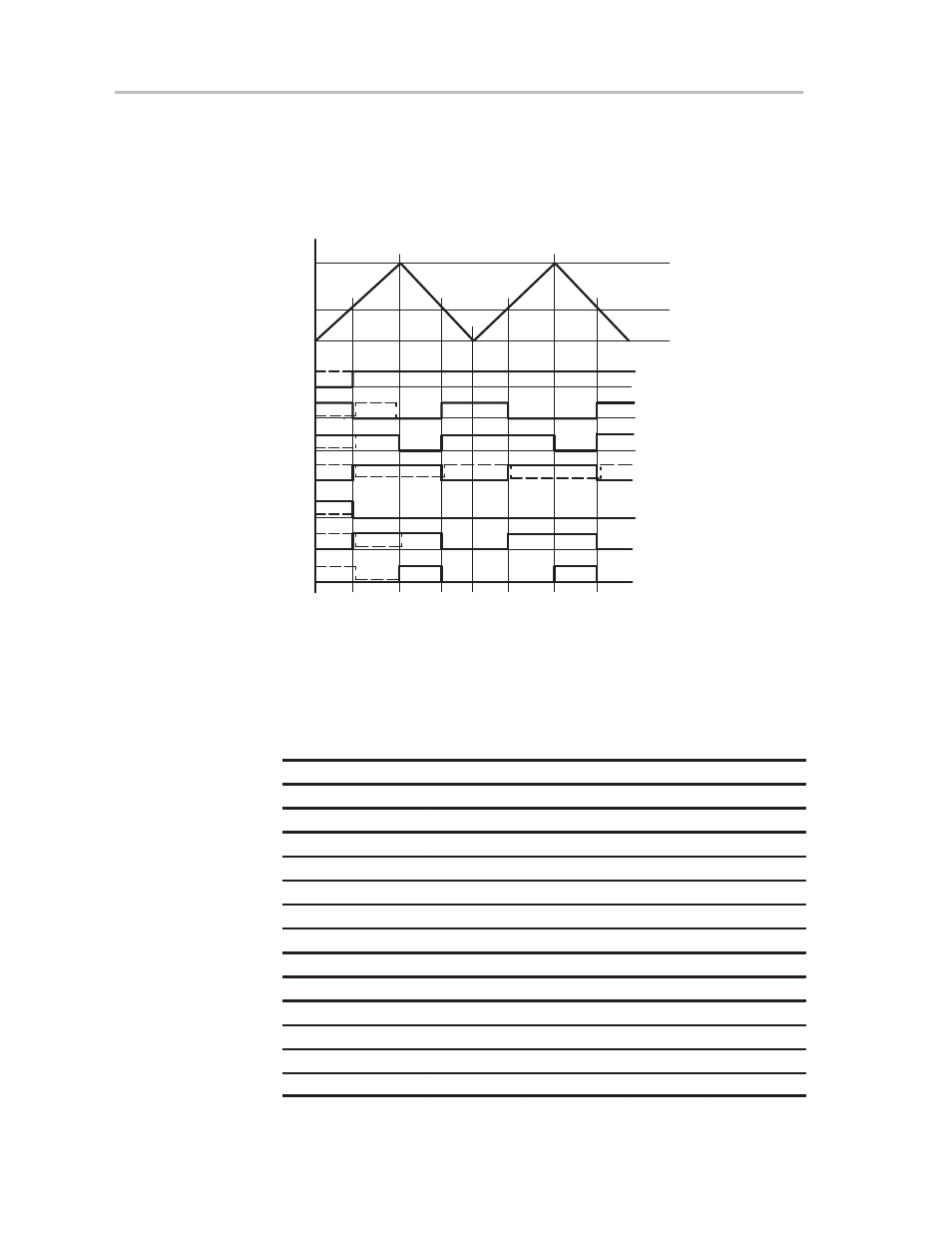
10.5.3.3 Output Examples—Timer in Up/Down Mode
The OUTx signal changes when the timer equals CCRx in either count
direction and when the timer equals CCR0, depending on the output mode, as
shown in Figure 10–26.
Figure 10–26. Output Examples—Timer in Up/Down Mode (I)
0FFFFh
CCR0
CCR3
0h
TIMOV
EQU3
EQU0
Output Mode 1: Set
Output Mode 2: PWM Toggle/Reset
Output Mode 3: PWM Set/Reset
Output Mode 4: Toggle
Output Mode 5: Reset
Output Mode 6: PWM Toggle/Set
Output Mode 7: PWM Reset/Set
EQU3
TIMOV
EQU3
EQU0
EQU3
Interrupt Events
10.6 Timer_A Registers
The Timer_A registers, described in Table 10–3, are word-structured and must
be accessed using word instructions.
Table 10–3.Timer_A Registers
Register
Short Form
Register Type
Address
Initial State
Timer_A control
TACTL
Read/write
160h
POR reset
Timer_A register
TAR
Read/write
170h
POR reset
Cap/com control 0
CCTL0
Read/write
162h
POR reset
Capture/compare 0
CCR0
Read/write
172h
POR reset
Cap/com control 1
CCTL1
Read/write
164h
POR reset
Capture/compare 1
CCR1
Read/write
174h
POR reset
Cap/com control 2
CCTL 2
Read/write
166h
POR reset
Capture/compare 2
CCR2
Read/write
176h
POR reset
Cap/com control 3
†
CCTL3
Read/write
168h
POR reset
Capture/compare 3
†
CCR3
Read/write
178h
POR reset
Cap/com control 4
†
CCTL4
Read/write
16Ah
POR reset
Capture/compare 4
†
CCR4
Read/write
17Ah
POR reset
Interrupt vector
TAIV
Read
12Eh
(POR reset)
† 14x devices only