Texas Instruments MSP430x1xx User Manual
Page 398
Instruction Set Overview
B-48
* RLC[.W]
Rotate left through carry
* RLC.B
Rotate left through carry
Syntax
RLC
dst or
RLC.W
dst
RLC.B
dst
Operation
C <– MSB <– MSB–1 .... LSB+1 <– LSB <– C
Emulation
ADDC
dst,dst
Description
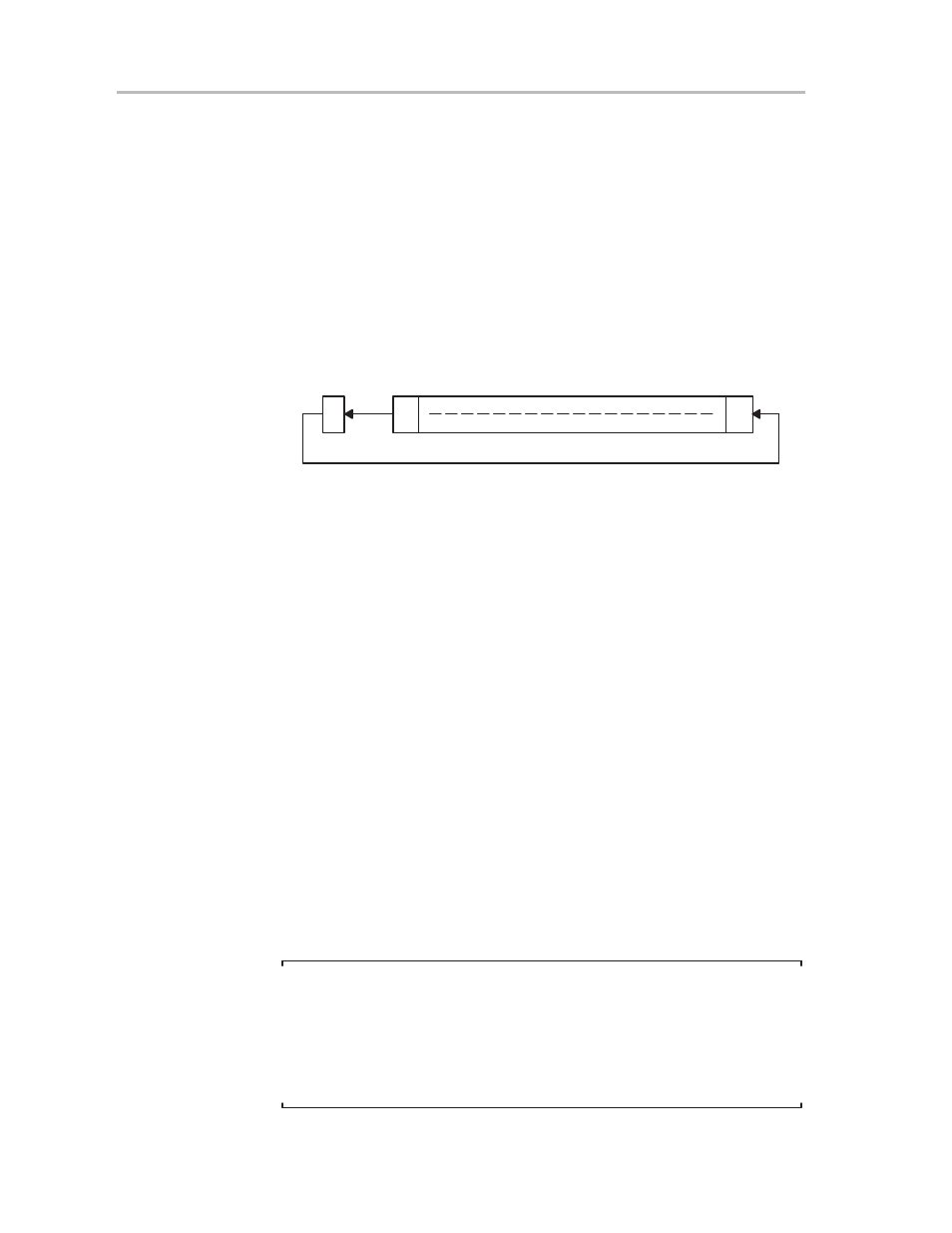
The destination operand is shifted left one position as shown in Figure B–7.
The carry bit (C) is shifted into the LSB and the MSB is shifted into the carry
bit (C).
Figure B–7.Destination Operand—Carry Left Shift
15
0
7
0
C
Byte
Word
Status Bits
N: Set if result is negative, reset if positive
Z: Set if result is zero, reset otherwise
C: Loaded from the MSB
V: Set if arithmetic overflow occurs, reset otherwise
Set if 03FFFh < dst
initial
< 0C000h, reset otherwise
Set if 03Fh < dst
initial
< 0C0h, reset otherwise
Mode Bits
OscOff, CPUOff, and GIE are not affected.
Example
R5 is shifted left one position.
RLC
R5
; (R5 x 2) + C –> R5
Example
The input P0IN.1 information is shifted into the LSB of R5.
BIT.B
#2,&P0IN
; Information –> Carry
RLC
R5
; Carry=P0in.1 –> LSB of R5
Example
The MEM(LEO) content is shifted left one position.
RLC.B
LEO
; Mem(LEO) x 2 + C –> Mem(LEO)
Example
The input P0IN.1 information is to be shifted into the LSB of R5.
BIT.B
#2,&P0IN
; Information –> Carry
RLC.B
R5
; Carry = P0in.1 –> LSB of R5
; High byte of R5 is reset
Note:
RLC and RLC.B Emulation
The assembler does not recognize the instruction:
RLC
@R5+.
It must be substituted by:
ADDC
@R5+,–2(R5).