Texas Instruments MSP430x1xx User Manual
Page 307
Conversion Modes
15-17
ADC12
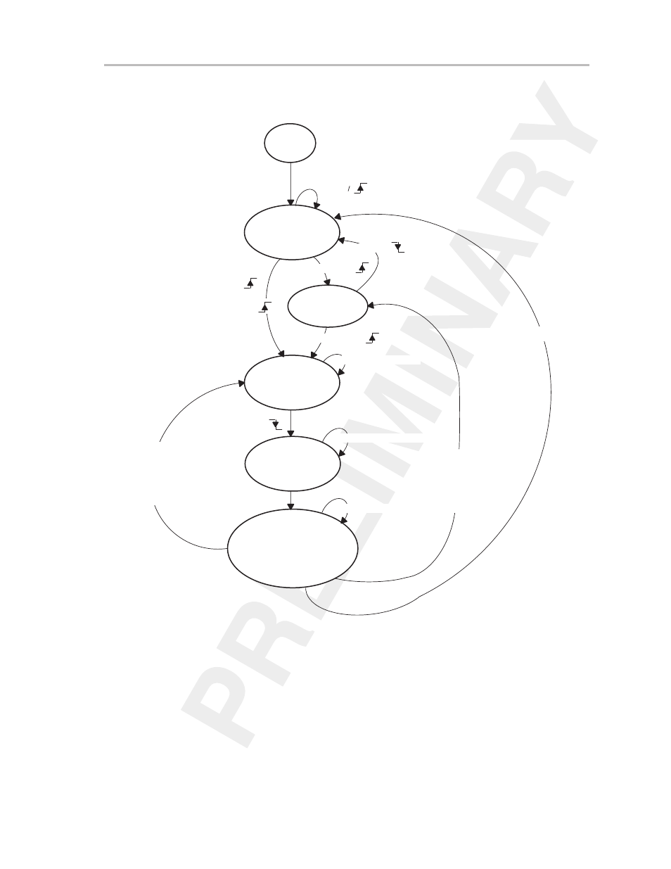
An illustration of repeat-single-channel mode is shown in Figure 15–11.
Figure 15–11.Repeat-Single-Channel Mode
ADC12
off
x = CStartAdd
Wait for Enable
ENC =
Wait for Trigger
Sample, Input
Channel Defined in
ADC12MCTLx
ENC =
ENC =
SHS = 0
and
ENC =
and
ADC12SC =
SAMPCON =
SAMPCON = 1
Convert, Use
12 x ADC12CLK
SAMPCON =
< 12 x ADC12CLK
Conversion
Completed,
Result Stored Into
ADC12MEMx,
ADC12IFG.x is Set
1 x ADC12CLK
ADC12ON = 1
CONSEQ = 2
MSC = 1
and
SHP = 1
and
ENC = 1
ENC = 0
(MSC = 0
or
SHP = 0)
and
ENC = 1
15.5.4 Repeat-Sequence-of-Channels Mode
The repeat-sequence-of-channel mode is identical to the sequence-of-
channel mode, except the sequence is repeated continuously until stopped by
software. Each time a conversion is completed, the results are loaded into the
appropriate ADC12MEMx register and the corresponding interrupt flag
ADC12IFG.x is set to indicate completion of the conversion. Additionally, If the
appropriate interrupt-enable flags are set, an interrupt request is generated
(see the
ADC12 Interrupt Vector Register ADC12IV section).
The conversion mode may be changed without first stopping the conversions.
When this is done, the new mode takes effect after the current sequence com-