Figure 10–33. uart implementation – Texas Instruments MSP430x1xx User Manual
Page 174
Timer_A UART
10-34
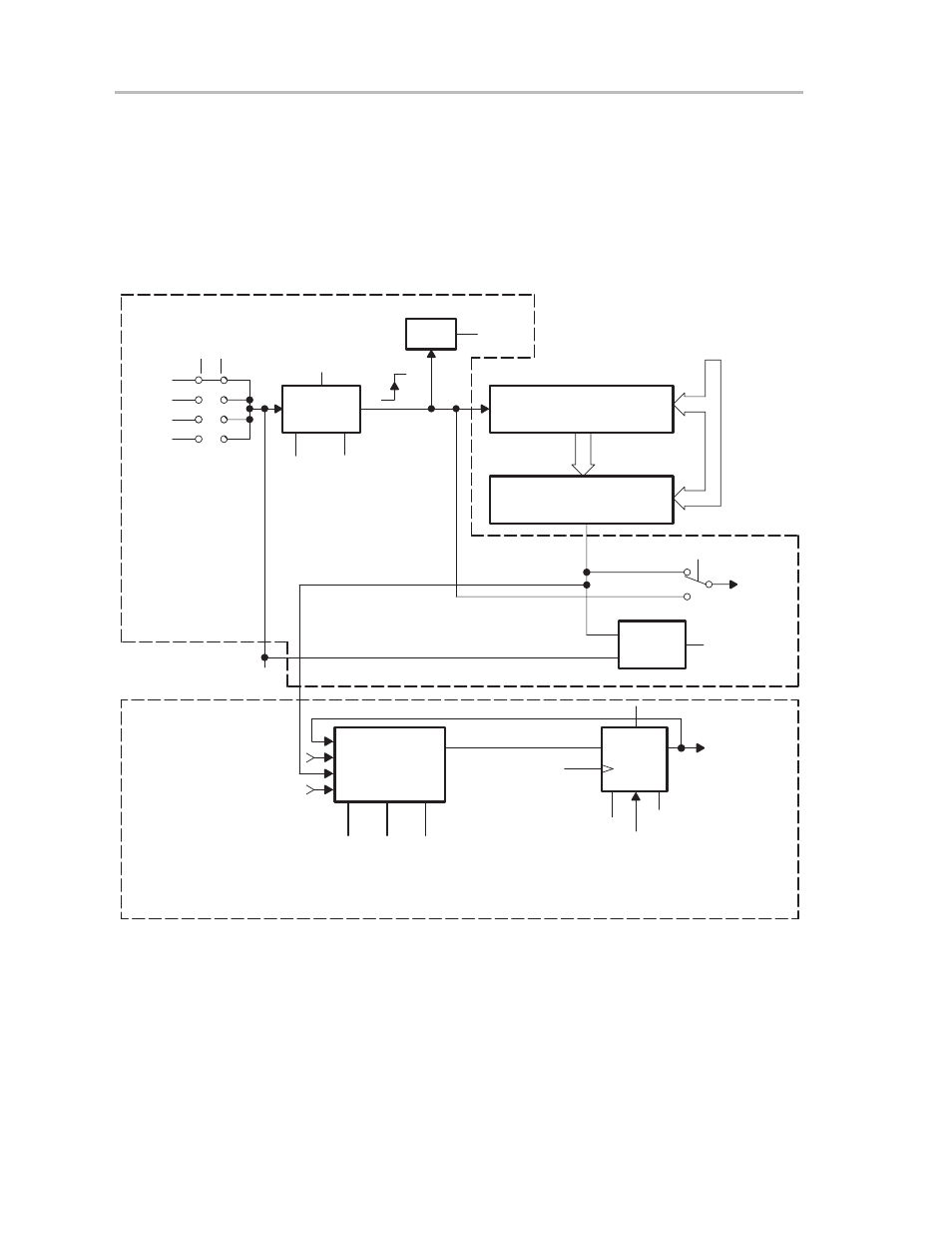
The receive feature uses one capture/compare function to shift pin data into
memory through bit SCCIx. The receive start time is recognized by capturing
the timer data with the negative edge of the input signal. The same
capture/compare block is then switched to compare mode and the receive bits
are latched automatically with the EQUx signal. The interrupt routine collects
the bits for later software processing. Figure 10–33 illustrates the UART
implementation.
Figure 10–33. UART Implementation
Set, EQUx set OUTx signal clock synchronized with timer clock
Reset, EQUx resets OUTx signal clock synchronized with
timer clock
Capture
Mode
EN
CCISx0
CCISx1
CCIxA
CCIxB
GND
0
1
2
3
VCC
CCMx1
CCMx0
Capture/Compare Register
CCRx
Set_CCIFGx
0
0
1
1
0
1
0
1
Disabled
Positive Edge
Negative Edge
Both Edges
Logic
15
0
Comparator x
0
1
CAPx
A
Y
CCIx
SCCIx
Timer Bus
COVx
Overflow x
CAPx
D
Q
Reset
Transmit Data Path
Set
Timer Clock
OUTx Signal
0
1
0
0
1
1
OMx2
OMx0
OMx1
Capture
EQUx
Receive Data Path