Texas Instruments MSP430x1xx User Manual
Page 418
Flash Memory Data Structure and Operation
C-6
C.2.1 Flash Memory Basic Functions
The basic functions of flash memory are to:
-
Supply program code and data during program execution
-
Erase, under software or JTAG control, parts of a module (one segment),
multiple segments, or an entire module.
-
Write data to a memory location under software or JTAG control. A double-
speed programming sequence is implemented within a 64-byte section of
the address range xx00h to xx3fh.
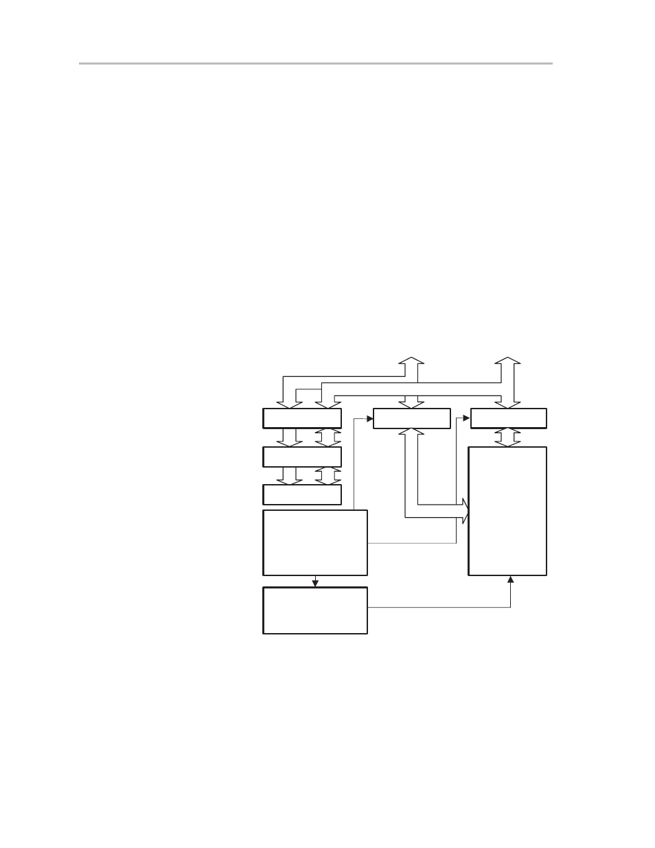
C.2.2 Flash Memory Block Diagram
The flash memory module has a minimum of three control registers, a timing
generator, a voltage generator to supply program and erase voltages, and the
flash memory itself. Data and address are latched when execution of a write
(program) or erase operation is in progress.
Figure C–5.Flash Memory Module Block Diagram
Enable
Data Latch
Enable
Address
Latch
Address Latch
Data Latch
MAB
MDB
FCTL1
FCTL2
FCTL3
Timing
Generator
Programming
Voltage
Generator
Flash
Memory
Array
C.2.3 Flash Memory, Basic Operation
The flash memory module works in read mode most of the time, the address
and data latch are transparent, and the timing generator and programming
voltage generator are off. The flash memory module changes its mode of
operation when data is written (programmed) to the module, or when the flash
memory, or parts of it, are erased. In these situations, flash control registers
FCTL1, FCTL2, and FCTL3 need to be set up properly to ensure correct write