Figure 11–8. new period < old period, 3 timer—continuous mode, Figure 11–9. timer continuous mode – Texas Instruments MSP430x1xx User Manual
Page 186
Timer Modes
11-10
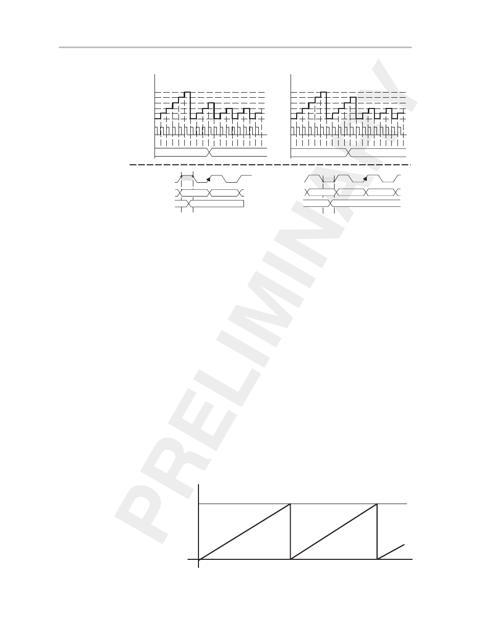
Figure 11–8. New Period < Old Period
TBCL0old = 5
TBCL0new = 2
Timer
Register
5
4
3
2
1
0
0 1 2 3 4 5 0 1 2 3 0 1 2 0 1 2 0 1
5
2
0 1 2 3 4 5 0 1 2 3 4 0 1 2 0 1 2 0 1
5
2
Timer
Register
5
4
3
2
1
0
TBCL0old = 5
TBCL0new = 2
TBCL0
TBCL0
TBCL0 Loaded With 2 During High Clock Phase
TBCL0 Loaded With 2 During Low Clock Phase
Timer Clock
Timer
TBCL0
Timer Clock
Timer
TBCL0
n
0 or n–1†
TBCLold
TBCLnew
TBCLold
TBCLnew
n
n+1
0 or n†
Load New TBCL0
During High Phase of Clock
Load New TBCL0
During Low Phase of Clock
†
Up mode: 0; up/down mode: n–1
†
Up mode: 0; up/down mode: n
11.3.3 Timer—Continuous Mode
The continuous mode is used if the timer period of TBR
(max)
clock cycles is
used for the application. A typical application of the continuous mode is to
generate multiple, independent timings. In continuous mode, the capture/
compare block 0 works in the same way as the other capture/compare blocks.
The capture/compare blocks and different output modes of each output unit
are useful to capture timer data based on external events or to generate
various different types of output signals. Examples of the different output
modes used with timer-continuous mode are shown in Figure 11–25.
In continuous mode, the timer starts counting from its present value. The
counter counts up to TBR
(max)
and restarts by counting from zero as shown
in Figure 11–9.
The maximum value of TBR [TBR
(max)
] in continuous mode is:
0FFFFh for 16-bit configuration
00FFFh for 12-bit configuration
003FFh for 10-bit configuration
000FFh for 8-bit configuration
Figure 11–9. Timer Continuous Mode
TBR
(max)
0h