Figure 15–22. extended-sample mode example timing, 4 using the msc bit – Texas Instruments MSP430x1xx User Manual
Page 317
Sampling
15-27
ADC12
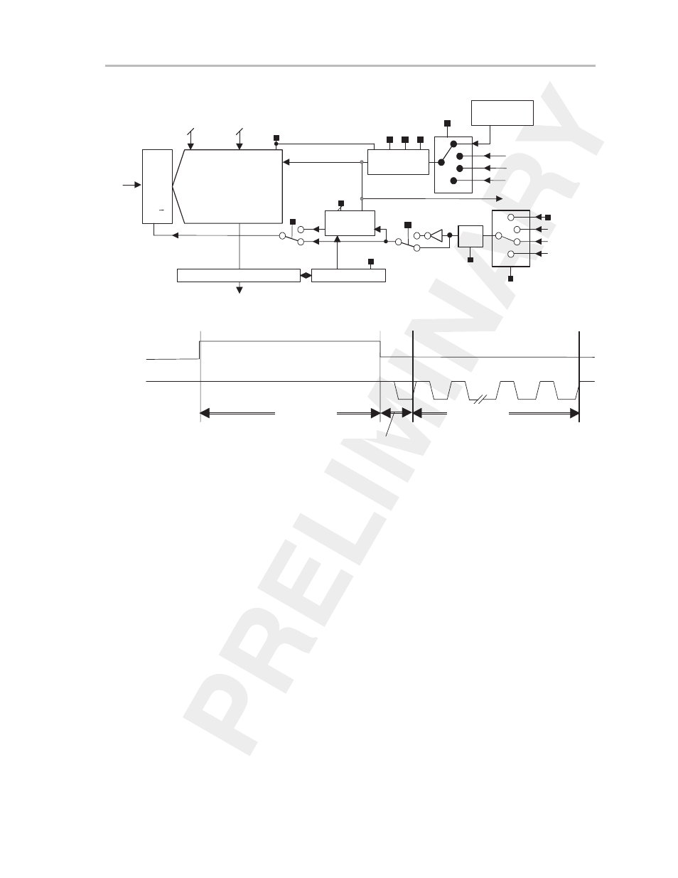
Figure 15–21. Extended-Sample Mode Example Configuration
ACLK
MCLK
SMCLK
ADC12OSC
Internal
Oscillator
ADC12CLK
S/H
Divide by
1,2,3,4,5,6,7,8
Sampling
Timer
12–bit S A R
ADC12DIV
ISSH
SHP
SHT1
SHT0
ADC12ON
ADC12SSEL
12–bit A/D converter core
analog
input
signal
Conversion CTL
SAMPCON
SHI
MSC
SHS
ENC
ADC12SC
Timer_A.OUT1
Timer_B.OUT0
Timer_B.OUT1
SYNC
Sample
and
Hold
VR–
VR+
Figure 15–22. Extended-Sample Mode Example Timing
t
sync
t
sample
t
convert
Timer_B.OUT0
ADC12CLK
15.7.4 Using the MSC Bit
The multiple-sample-and-conversion (MSC) control bit is not used if the sam-
ple signal SAMPCON is generated without the sampling timer. However, when
the sampling timer is used to generate the SAMPCON signal and the operating
mode is other than single-channel single-conversion (CONSEQ > 0), the MSC
bit can be used to configure the converter to perform the successive conver-
sions automatically and as quickly as possible.
If MSC = 0, then a rising edge of the SHI signal is required to trigger each sam-
ple-and-conversion, regardless of what mode the converter is in. When MSC
= 1 and CONSEQ > 0, the first rising edge of the SHI signal triggers the first
conversion, but successive conversions are triggered automatically as soon
as the prior conversion is completed. Additional rising edges on SHI are ig-
nored until the sequence is completed or until the ENC bit is toggled (depend-
ing on mode). The function of the ENC bit is unchanged when using the MSC
bit. See Figures 15–23 and 15–24.