Texas Instruments MSP430x1xx User Manual
Page 222
Asynchronous Operation
12-6
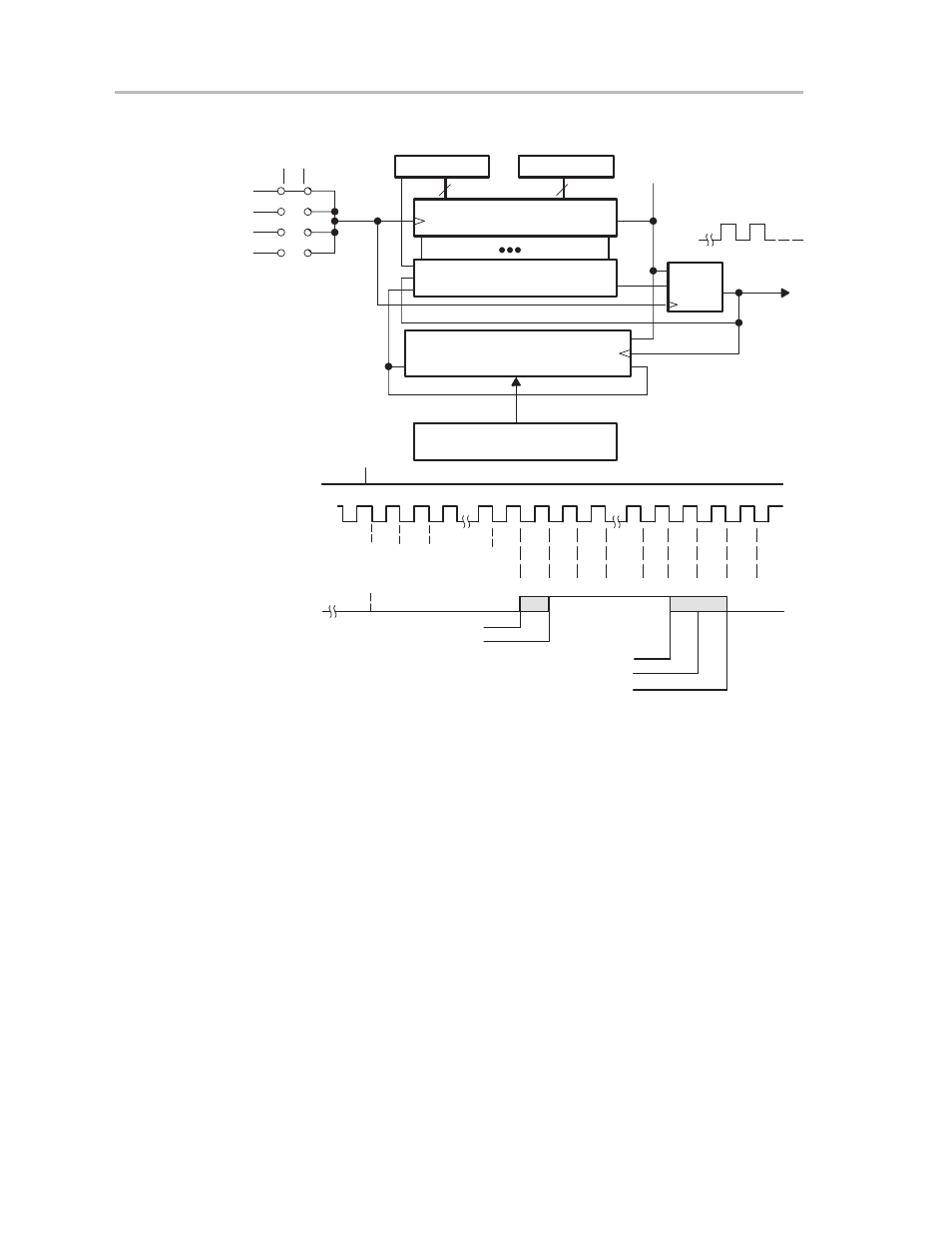
Figure 12–6. MSP430 Baud Rate Generation. Example for n or n + 1 Clock Periods
0
SSEL0
SSEL1
UCLKI
ACLK
1
2
3
15-Bit Prescaler/Divider
Toggle
FF
Start
7
8
15
BITCLK
UBR0
UBR1
0
7
0
7
1
Q1
Q15
Compare 0 or 1
Shift Modulation Register Data
Shift_in
Shift_out
m
Modulation Register UMOD
7
0
BRCLK
INT(n/2), m = 0
INT(n/2)+m(=1)
n(Even), m = 0
n(Odd) or n(Even)+m(=1)
n(Odd)+m(=1)
H
L
H
L
H
L
Start
BRCLK
Counter
BITCLK
Divide By
n/2-2
n/2 n/2-1
1
1
1
0
n/2
n/2
n/2
n/2-1
n/2-1
n/2-1
n/2-2
n/2-2
2
1
1
1
0
n/2
0
n/2
n/2-1
n/2
n/2-1
n/2-2
SMCLK
SMCLK
The modulation register LSB is first used for modulation, which begins with the
start bit. A set modulation bit increases the division factor by one.
Example 12–1. 4800 Baud
Assuming a clock frequency of 32,768 Hz for the BRCLK signal and a required
baud rate of 4800, the division factor is 6.83. The baud rate generation in the
MSP430 USART uses a factor of six plus a modulation register load of 6Fh
(0110 1111). The divider runs the following sequence: 7 – 7 – 7 – 7 – 6 –
7 – 7 – 6 and so on. The sequence repeats after all eight bits of the modulator
are used.
Example 12–2. 19,200 Baud
Assuming a clock frequency of 1.04 MHz (32
×
32,768 Hz) for the BRCLK
signal and a required baud rate of 19,200, the division factor is 54.61. The baud
rate generation in the MSP430 USART uses a factor of 54 (36h) plus a
modulation register load of 0D5h. The divider runs the following sequence: 55
– 54 – 55 – 54 – 55 – 54 – 55 – 55, and so on. The sequence repeats after all
eight bits of the modulator are used.