Texas Instruments MSP430x1xx User Manual
Page 145
Timer_A Operation
10-5
Timer_A
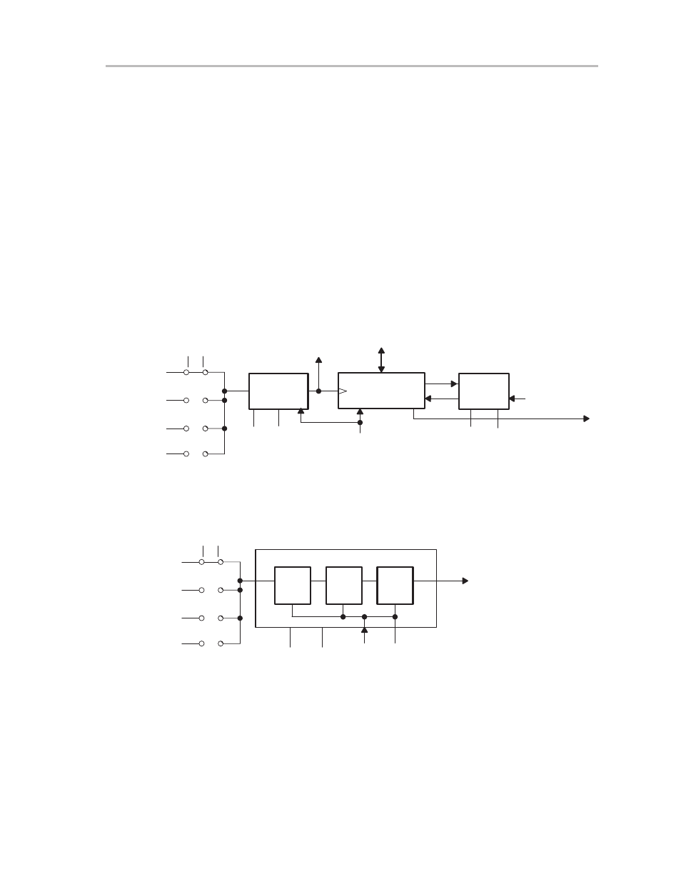
10.2.2 Clock Source Select and Divider
The timer clock can be sourced from internal clocks (i.e. ACLK or SMCLK) or
from an external source (TACLK) as shown in Figure 10–3. The clock source
is selectable with the SSEL0 and SSEL1 bits in the TACTL register. It is impor-
tant to note that when changing the clock source for the timer, errant timings
can occur. For this reason stopping the timer before changing the clock source
is recommended.
The selected clock source may be passed directly to the timer or divided by
2,4, or 8, as shown in Figure 10–4. The ID0 and ID1 bits in the TACTL register
select the clock division. Note that the input divider is reset by a POR signal
(see chapter 3,
System, Resets, Interrupts, and Operating Modes for more in-
formation on the POR signal) or by setting the CLR bit in the TACTL register.
Otherwise, the input divider remains unchanged when the timer is modified.
The state of the input divider is invisible to software.
Figure 10–3. Schematic of 16-Bit Timer
Input
Divider
CLK
16-Bit Timer
SSEL0
SSEL1
TACLK
ACLK
SMCLK
0
1
2
3
RC
INCLK
ID1
ID0
0
15
Data
Timer Clock
POR/CLR
Mode
Control
MC1
MC0
Equ0
Carry/Zero
Set_TAIFG
0
0
1
1
0
1
0
1
Pass
1/2
1/4
1/8
0
0
1
1
0
1
0
1
Stop Mode
Up Mode
Continuous Mode
Up/Down Mode
Figure 10–4. Schematic of Clock Source Select and Input Divider
T
Q
16-Bit Timer Clock
ID1
C
T
Q
C
T
Q
C
ID0
POR
CLR
0
0
1
1
0
1
0
1
Pass
1/2
1/4
1/8
Input Divider
SSEL0
SSEL1
TACLK
ACLK
SMCLK
0
1
2
3
INCLK