Texas Instruments MSP430x1xx User Manual
Page 117
Features for Low-Power Applications
7-17
Basic Clock Module
JNC
Retest
BIC.B
#OFIFG,&IFG1 ; Clear osc. fault int. flag
BIS.B
#(SELM1+SELM0),&BCSCTL2 ; Select now LFXT1 clock
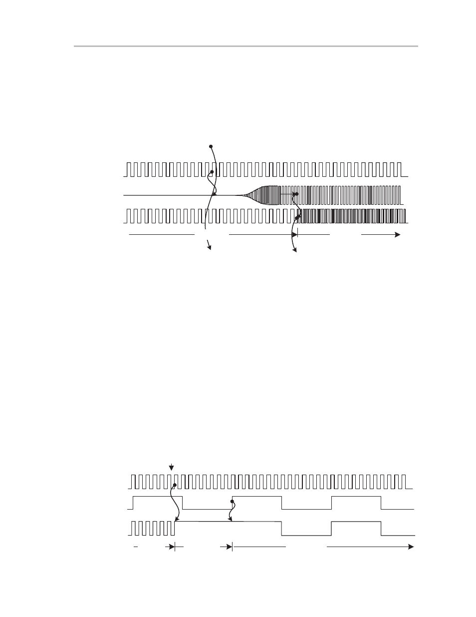
Figure 7–15. Timing to Select Crystal Oscillator for MCLK, Example Uses LFXT1 in HF
Mode for MCLK
If Crystal Oscillator settled
Then Select Crystal Oscillator
for MCLK
DCOCLK
XT1CLK
MCLK
XT1CLK
DCOCLK
Turn on the
Crystal Oscillator
7.4.5
Synchronization of Clock Signals
The clock signals MCLK and SMCLK can be supplied by different clock
sources. While switching from one clock source to the other, the switch is syn-
chronized to avoid critical race conditions. When another clock source is se-
lected the following occurs in order:
1) The current clock cycle continues until the next rising edge.
2) The clock then remains high until the next rising edge of the newly selected
clock.
3) Now the new clock source is selected and continues with a full high period.
Figure 7–16. Select Another Clock Source Signal, Example Switches From DCOCLK to
LFXT1CLK for Clock MCLK
DCOCLK
LFXT1CLK
MCLK
LFXT1CLK
DCOCLK
Select
LFXT1CLK
Wait for
+LFXT1CLK