Texas Instruments MSP430x1xx User Manual
Page 296
Analog Inputs and Multiplexer
15-6
Warning ! Reference Voltage Settling Time
When the built-in reference is turned on with the VREFON bit, the
settling timing noted in the data sheet must be observed before
starting a conversion. Otherwise, the results will be false until the
reference settles. Once all internal and external references have
settled, no additional settling time is required when selecting or
changing the conversion range for each channel.
15.3 Analog Inputs and Multiplexer
15.3.1 Analog Multiplexer
The eight external analog input channels and four internal signals are selected
as the channel for conversion by the analog multiplexer. Channel selection is
made for each conversion-memory register with the corresponding
ADC12MCTLx register. The input multiplexer is a break-before-make type
(shown in Figure 15–3) to reduce input-to-input noise injection resulting from
channel switching. The input multiplexer is also a T-switch to minimize the cou-
pling between channels. Channels that are not selected are isolated from the
A/D and the intermediate node is connected to analog ground (AV
SS
) so that
the stray capacitance is grounded to help eliminate crosstalk.
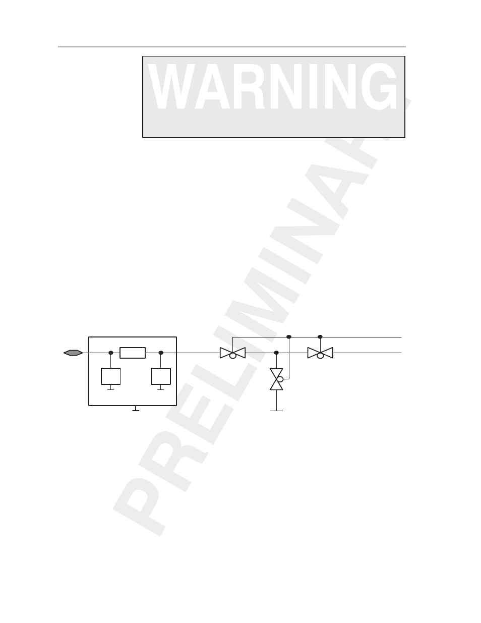
Figure 15–3. Analog Multiplexer Channel
R ~ 100Ohm
ESD protection
ADC12MCTLx.0–3
Input
Crosstalk can exist because there is always some parasitic coupling capaci-
tance across the switch and between switches. This can take several forms,
such as coupling from the input to the output of an off switch, or coupling from
an off analog input channel to the output of an adjacent on channel. For high-
accuracy conversions, crosstalk interference should be minimized by shield-
ing and other well-known printed-circuit board (PCB) layout techniques.