2 timer_a operation – Texas Instruments MSP430x1xx User Manual
Page 144
Timer_A Operation
10-4
10.2 Timer_A Operation
The 16-bit timer has 4 modes of operation selectable with the MC0 and MC1
bits in the TACTL register. The timer increments or decrements (depending on
mode of operation) with each rising edge of the clock signal. The timer can be
read or written to with software. Additionally, the timer can generate an inter-
rupt with its ripple-carry output when it overflows.
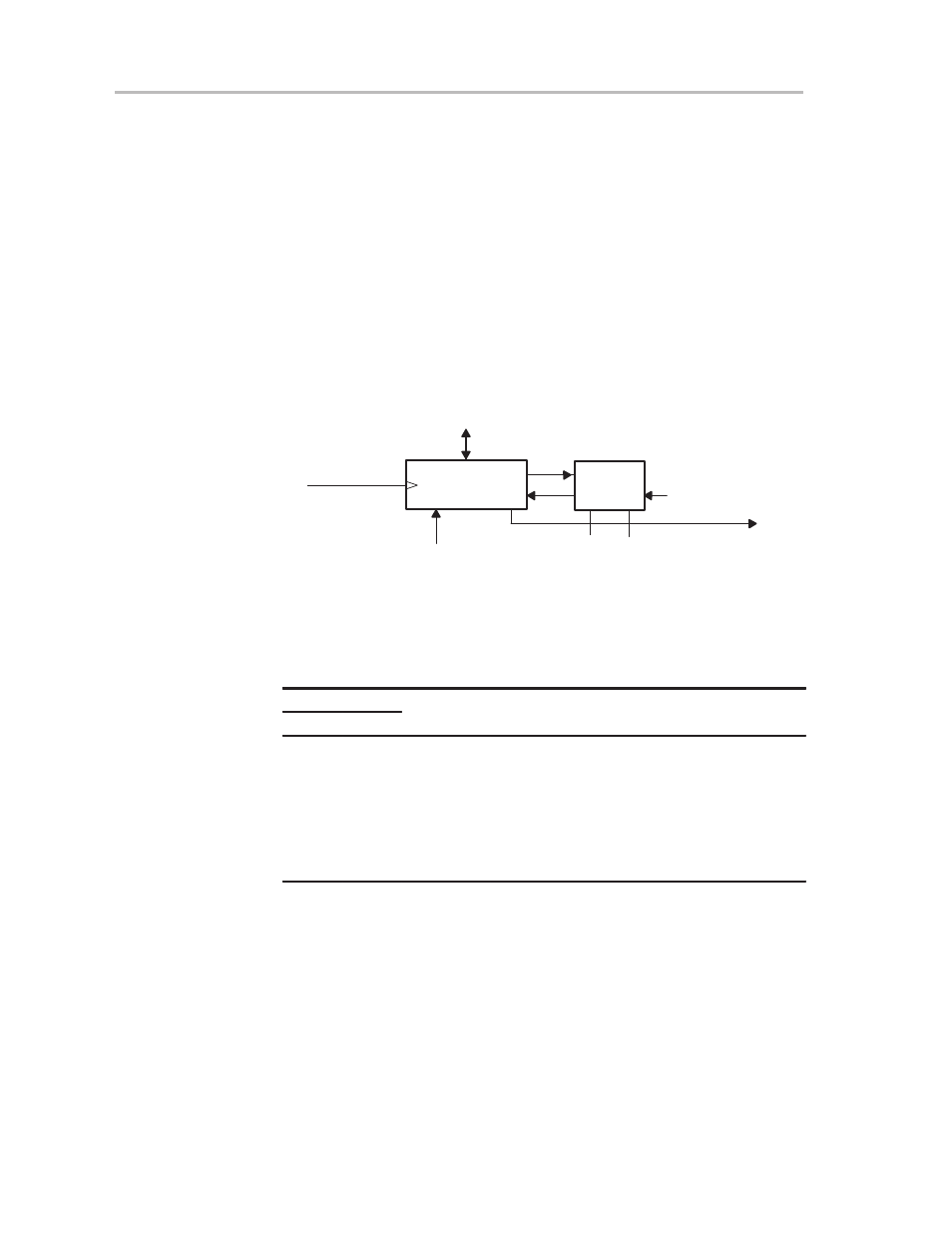
10.2.1 Timer Mode Control
The timer has four modes of operation as shown in Figure 10–2 and described
in Table 10–1: stop, up, continuous, and up/down. The operating mode is soft-
ware selectable with the MC0 and MC1 bits in the TACTL register.
Figure 10–2. Mode Control
CLK
16-Bit Timer
RC
15
0
Data
POR
Mode
Control
MC1
MC0
Equ0
Carry/Zero
Set_TAIFG
0
0
1
1
0
1
0
1
Stop Mode
Up Mode
Continuous Mode
Up/Down Mode
Timer Clock
Table 10–1.Timer Modes
Mode Control
MC1
MC0
Mode
Description
0
0
Stop
The timer is halted.
0
1
Up
The timer counts upward until value is equal to
value of compare register CCR0.
1
0
Continuous
The timer counts upward continuously.
1
1
Up/Down
The timer counts up until the timer value is
equal to compare register 0 and then it counts
down to zero.