1 master spi mode – Texas Instruments MSP430x1xx User Manual
Page 253
Synchronous Operation
13-7
USART Peripheral Interface, SPI Mode
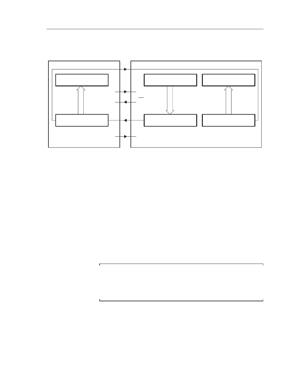
Figure 13–6 illustrates the USART module functioning as a slave in a three or
four-pin SPI configuration.
Figure 13–6. MSP430 USART as Slave in Three-Pin or Four-Pin Configuration
Receive Buffer URXBUF
Receive Shift Register
LSB
MSB
Transmit Buffer UTXBUF
Transmit Shift Register
LSB
MSB
SPI Receive Buffer
Data Shift Register DSR
LSB
MSB
SOMI
SOMI
SIMO
SIMO
MASTER
SLAVE
Px.x
STE
STE
SS
Port.x
UCLK
SCLK
MSP430 USART
COMMON SPI
13.3.1 Master SPI Mode
The master mode is selected when the master-mode bit (MM) in control
register UCTL is set. The USART module controls the serial-communication
network by providing UCLK at the UCLK pin. Data is output on the SIMO pin
during the first UCLK period and latched from the SOMI pin in the middle of
the corresponding UCLK period.
The data written to the transmit buffer (UTXBUF) is moved to the transmit shift
register as soon as the shift register is empty. This initiates the data transfer
on the SIMO pin starting with the most-significant bit. At the same time,
received data is shifted into the receive shift register and, upon receiving the
selected number of bits, the data is transferred to the receive buffer (URXBUF)
setting the receive interrupt flag (URXIFG). Data is shifted into the receive shift
register starting with the most-significant bit. It is stored and right-justified in
the receive buffer (URXBUF). When previous data is not read from the receive
buffer (URXBUF), the overrun error bit (OE) is set.
Note:
USART Synchronous Master Mode, Receive Initiation
The master writes data to the transmit buffer UTXBUF to receive a character.
The receive starts when the transmit shift register is empty and the data is
transferred to it. Receive and transmit operations always take place together,
at opposite clock edges.
The protocol can be controlled using the transmit-interrupt flag UTXIFG, or the
receive-interrupt flag URXIFG. By using UTXIFG immediately after sending
the shift-register data to the slave, the buffer data is transferred to the shift
register and the transmission starts. The slave receive timing should ensure
that there is a timely pick-up of the data. The URXIFG flag indicates when the
data shifts out and in completely. The master can use URXIFG to ensure that
the slave is ready to correctly receive the next data.