3 timer—continuous mode, Figure 10–9. timer—continuous mode, Figure 10–10. continuous mode flag setting – Texas Instruments MSP430x1xx User Manual
Page 149
Timer Modes
10-9
Timer_A
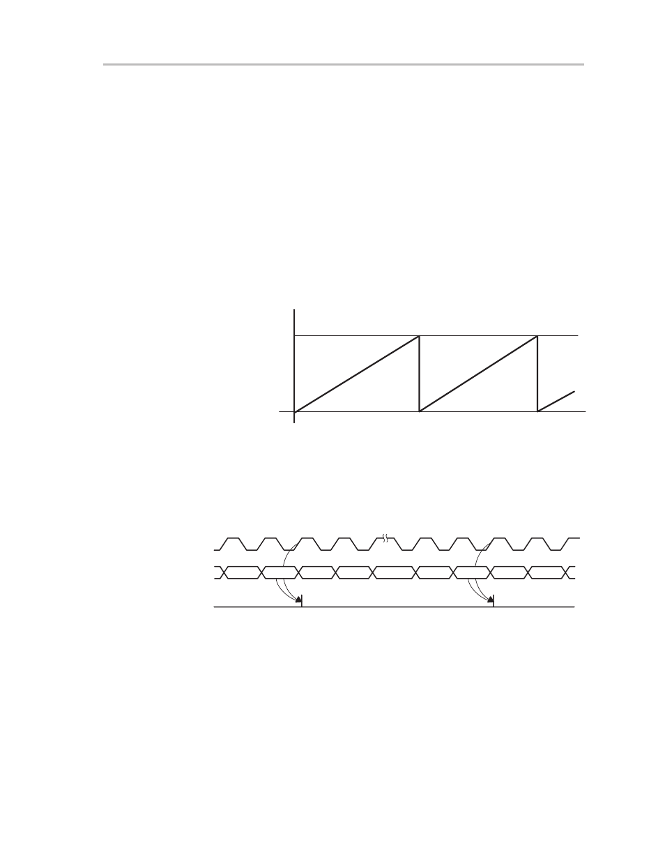
10.3.3 Timer—Continuous Mode
The continuous mode is used if the timer period of 65,536 clock cycles is used
for the application. A typical application of the continuous mode is to generate
multiple, independent timings. In continuous mode, the capture/compare
register CCR0 works in the same way as the other compare registers.
The capture/compare registers and different output modes of each output unit
are useful to capture timer data based on external events or to generate
various different types of output signals. Examples of the different output
modes used with timer-continuous mode are shown in Figure 10–25.
In continuous mode, the timer starts counting from its present value. The
counter counts up to 0FFFFh and restarts by counting from zero as shown in
Figure 10–9.
Figure 10–9. Timer—Continuous Mode
0FFFFh
0h
The TAIFG flag is set when the timer
counts from 0FFFFh to zero. The interrupt
flag is set independently of the corresponding interrupt enable bit, as shown
in Figure 10–10. An interrupt is requested if the corresponding interrupt enable
bit and the GIE bit are set.
Figure 10–10. Continuous Mode Flag Setting
FFFE
FFFF
0h
1h
FFFE
0h
1h
Timer
Clock
Timer
Set Interrupt
Flag TAIFG
FFFF