3 timer modes – Texas Instruments MSP430x1xx User Manual
Page 184
Timer Modes
11-8
11.3 Timer Modes
11.3.1 Timer—Stop Mode
Stopping and starting the timer is done simply by changing the mode control
bits (MCx). The value of the timer is not affected.
When the timer is stopped from up/down mode and then restarted in up/down
mode, the timer counts in the same direction as it was counting before it was
stopped. For example, if the timer is in up/down mode and counting in the down
direction when the MCx bits are reset, when they are set back to the up/down
direction, the timer starts counting in the down direction from its previous
value. If this is not desired in an application, the CLR bit in the TBCTL register
can be used to clear this direction memory feature.
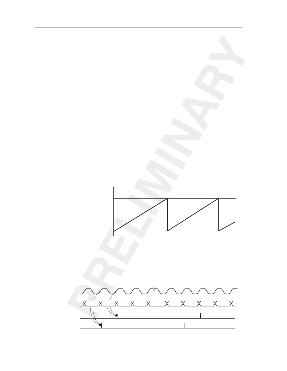
11.3.2 Timer—Up Mode
The up mode is used if the timer period must be different from the TBR
(max)
clock cycles of the continuous mode periods. The capture/compare register
CCR0 data defines the timer period.
The counter
counts up to the content of compare latch TBCL0, as shown in
Figure 11–5. When the timer value and the value of compare latch TBCL0 are
equal (or if the timer value is greater than the TBCL0 value), the timer restarts
counting from zero.
Figure 11–5. Timer Up Mode
TBR
(max)
0h
TBCL0
Flag CCIFG0 is set when the timer equals the TBCL0 value. The TBIFG flag
is set when the timer
counts from TBCL0 to zero. All interrupt flags are set
independently of the corresponding interrupt enable bit, but an interrupt is
requested only if the corresponding interrupt enable bit and the GIE bit are set.
Figure 11–6 shows the flag set cycle.
Figure 11–6. Up Mode Flag Setting
TBCL0–1
TBCL0
0h
1h
TBCL0–1
TBCL0
0h
1h
Timer Clock
Timer
Set Flag TBIFG
Set Flag CCIFG0