Figure 12–19. usart baud rate select register, Figure 12–20. usart modulation control register – Texas Instruments MSP430x1xx User Manual
Page 236
Control and Status Registers
12-20
calculation. The flag is disabled if parity generation and
detection are not enabled. In this case the flag is read as 0. It is
reset by a SWRST, a system reset, or by reading the URXBUF.
Bit 7:
The framing error flag bit FE is set when a character is received
with a 0 stop bit and is loaded into the receive buffer. Only the
first stop bit is checked when more than one is used. The missing
stop bit indicates that the start-bit synchronization is lost and the
character is incorrectly framed. FE is reset by a SWRST, a
system reset, or by reading the URXBUF.
Note:
Receive Status Control Bits
The receive status control bits FE, PE, OE, BRK, and RXWake are set by the
hardware according to the conditions of the characters received. Once the
bits are set, they remain set until the software resets them directly, or there
is a reading of the receive buffer. False character interpretation or missing-
interrupt capability can result in uncleared error bits.
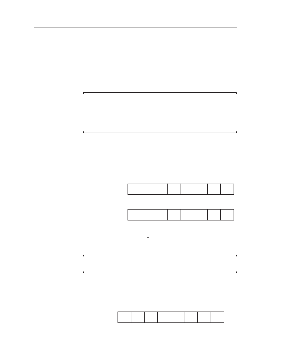
12.5.4 Baud Rate Select and Modulation Control Registers
The baud-rate generator uses the content of the baud-rate select registers
UBR0 and UBR1 shown in Figure 12–19, with the modulation control register
to generate the serial data-stream bit timing.
Figure 12–19. USART Baud Rate Select Register
27
7
0
UBR00, 074h
26
25
24
23
22
21
20
rw
215
7
0
UBR10, 075h
214
213
212
211
210
29
28
rw
rw
rw
rw
rw
rw
rw
rw
rw
rw
rw
rw
rw
rw
rw
UBR01, 07Ch
UBR11, 07Dh
Baud rate =
BRCLK
UBR
)
1
n
S
n–1
i
+
0
mi
with UBR= [UBR1,UBR0]
The baud-rate control register range is:
3
≤
UBR
<
0FFFFh
Note:
Unpredictable receive and transmission occur if UBR <3.
The modulation control register, shown in Figure 12–20, ensures proper timing
generation with the UBR0 and UBR01, even with crystal frequencies that are
not integer multiples of the required baud rate.
Figure 12–20. USART Modulation Control Register
7
0
UMCTL0, 073h
m5
m6
m4
m0
m3
m7
m1
m2
rw
rw
rw
rw
rw
rw
rw
rw
UMCTL1, 07Bh