Texas Instruments MSP430x1xx User Manual
Page 258
Interrupt and Control Functions
13-12
13.4.2.2 Receive/Transmit Enable, MSP430 is Slave
Figure
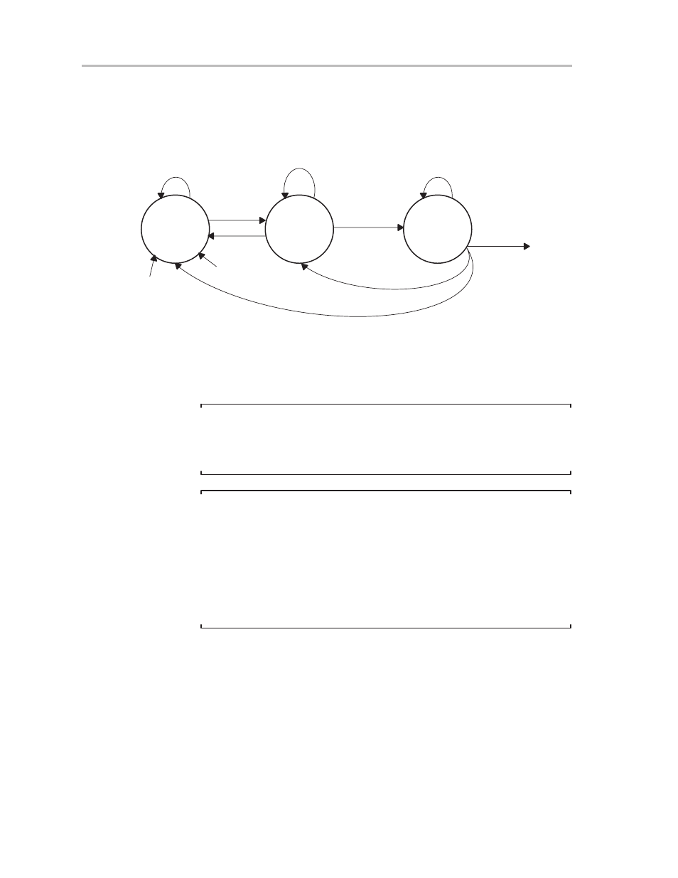
13–11 shows the receive/transmit-enable-bit activity when the
MSP430 is slave.
Figure 13–11.State Diagram of Transmit Enable—MSP430 as Slave
Idle State
(Transmitter
Enabled)
Transmit
Disable
Transmission
Active
USPIE = 0
No Clock at UCLK
Not Completed
USPIE = 1
USPIE = 1
USPIE = 0
USPIE = 1
Handle Interrupt
Conditions
Character
Transmitted
USPIE = 1
USPIE = 0
SWRST
PUC
External Clock
Present
When USPIE is reset, any data can be written regularly into the transmit buffer,
but no transmission is started. Once the USPIE bit is set, the data in the
transmit buffer are immediately loaded into the transmit shift register and
character transmission is started.
Note:
Writing to UTXBUF, SPI Mode
Data should never be written to transmit buffer UTXBUF when the buffer is
not ready (UTXIFG = 0) and the transmitter is enabled (USPIE is set). If data
is written, character shifting can be random.
Note:
Write to UTXBUF/Reset of Transmitter, SPI Mode
Disabling of the transmitter should be done only if all data to be transmitted
have been moved to the transmit shift register.
MOV.B
#....,&UTXBUF
BIC.B
#USPIE,&ME2
; If BITCLK < MCLK then the
; transmitter might be stopped
; before the buffer is loaded
; into the transmitter
; shift register