Figure 10–19. capture signal – Texas Instruments MSP430x1xx User Manual
Page 155
Timer Modes
10-15
Timer_A
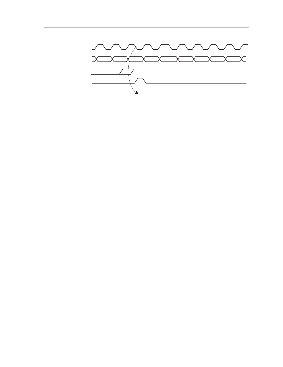
Figure 10–19. Capture Signal
n-2
Timer
Clock
Timer
Set
CCIFGx
Capture
ООО
ООО
n+1
CCIx
n-1
n+2
n+3
n+4
n+5
n+6
n
Applications with slow timer clocks can use the nonsynchronized capture
signal. In this scenario the software can validate the data and correct it if
necessary as shown in the following example:
; Software example for the handling of asynchronous
; capture signals
;
; The data of the capture/compare register CCRx are taken
; by the software in the according interrupt routine
; – they are taken only after a CCIFG was set.
; The timer clock is much slower than the system clock
; MCLK.
;
CCRx_Int_hand ...
; Start of interrupt
; handler
...
...
CMP
&CCRx,&TAR
; Test if the data
; CCRX = TAR
JEQ Data_Valid
MOV
&TAR,&CCRx
; The data in CCRx is
; wrong, use the timer data
Data_Valid
...
...
; The data in CCRx are valid
...
...
RETI
;
Overflow logic is provided with each capture/compare register to flag the user
if a second capture is performed before data from the first capture was read
successfully. Bit COVx in register CCTLx is set when this occurs as shown in
Figure 10–20.