3 asynchronous operation – Texas Instruments MSP430x1xx User Manual
Page 220
Asynchronous Operation
12-4
12.3 Asynchronous Operation
In the asynchronous mode, the receiver synchronizes itself to frames but the
external transmitting and receiving devices do not use the same clock source;
the baud rate is generated locally.
12.3.1 Asynchronous Frame Format
The asynchronous frame format, shown in Figure 12–3, consists of a start bit,
seven or eight data bits, an even/odd/no parity bit, an address bit in address
bit mode, and one or two stop bits. The bit period is defined by the selected
clock source and the data in the baud rate registers.
Figure 12–3. Asynchronous Frame Format
[Parity Bit, PENA = 1]
[Address Bit, MM = 1]
Mark
Space
D0
D6 D7 AD PA
SP SP
[Optional Bit, Condition]
[2nd Stop Bit, SP = 1]
[8th Data Bit, CHAR = 1]
ST
The receive (RX) operation is initiated by the receipt of a valid start bit. It begins
with a negative edge at URXD, followed by the taking of a majority vote from
three samples where two of the samples must be zero. These samples occur
at n/2–X, n/2, and n/2+X of the BRCLK periods following the negative edge.
This sequence provides false start-bit rejection, and also locates the center of
the bits in the frame, where the bits can be read on a majority basis. The timing
of X is
1
/
32
to
1
/
63
times that of the BRCLK, depending on the division rate of
the baud rate generator and provides complete coverage of at least two
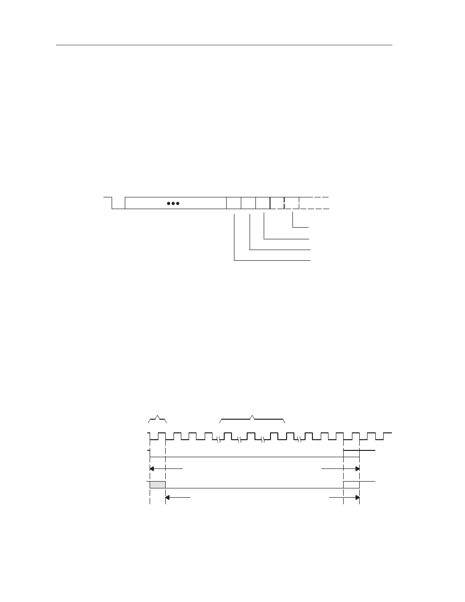
BRCLK periods. Figure 12–4 shows an asynchronous bit format.
Figure 12–4. Asynchronous Bit Format. Example for n or n + 1 Clock Periods
1
2
3
n/2–x
n/2
n/2+x
n–1
n
n+1
1
2
n–1
n
1
2
3
Falling Edge
on UEXD
Indicates Start bit
Majority Vote
Taken From
URXD Data Line
Data Bit Period = n or n+1 BRCLK Periods
Data Bit Period = n or n+1 BRCLK Periods
H
L
H
L
H
L
BRCLK
UTXD
URXD